 |
|||
|
|
|||
|
Page Title:
Section III MAINTENANCE PROCEDURES |
|
||
| ||||||||||
|
|
 TM 3-4240-302-30&P-6
Section III MAINTENANCE PROCEDURES
2-7. AIRFLOW VALVE.
This task covers the removal, repair, and installation of the following:
a.
e.
Diode and capacitor on S2 sensitive
b.
switch (p. 2-17)
c.
Diode and capacitor on S1 sensitive
f.
S2 sensitive switch and adapter (p. 2-18)
switch (p. 2-15)
g.
Wiring (p. 2-19)
d.
S1 sensitive switch and adapter (p. 2-16)
INITIAL SETUP
Tools
Equipment Condition
Electronic Equipment Tool Kit
Airflow valve removed from the filter unit or
TK-105/G
airflow valve removed from airflow valve and
silencer
References
TB SIG 222
NOTE
Troubleshooting References
Perform all electrical wiring connections in
Refer to page 2-2
accordance with wiring diagram on page 2-19.
Materials/Parts
Sealing compound (item 1, app C)
Lacing - Tape (item 2, app C)
Oil Varnish (item 3, app C)
LOCATION
ITEM
ACTION
REMOVAL
Airflow Valve
Motor with RFI filter FL2
1.
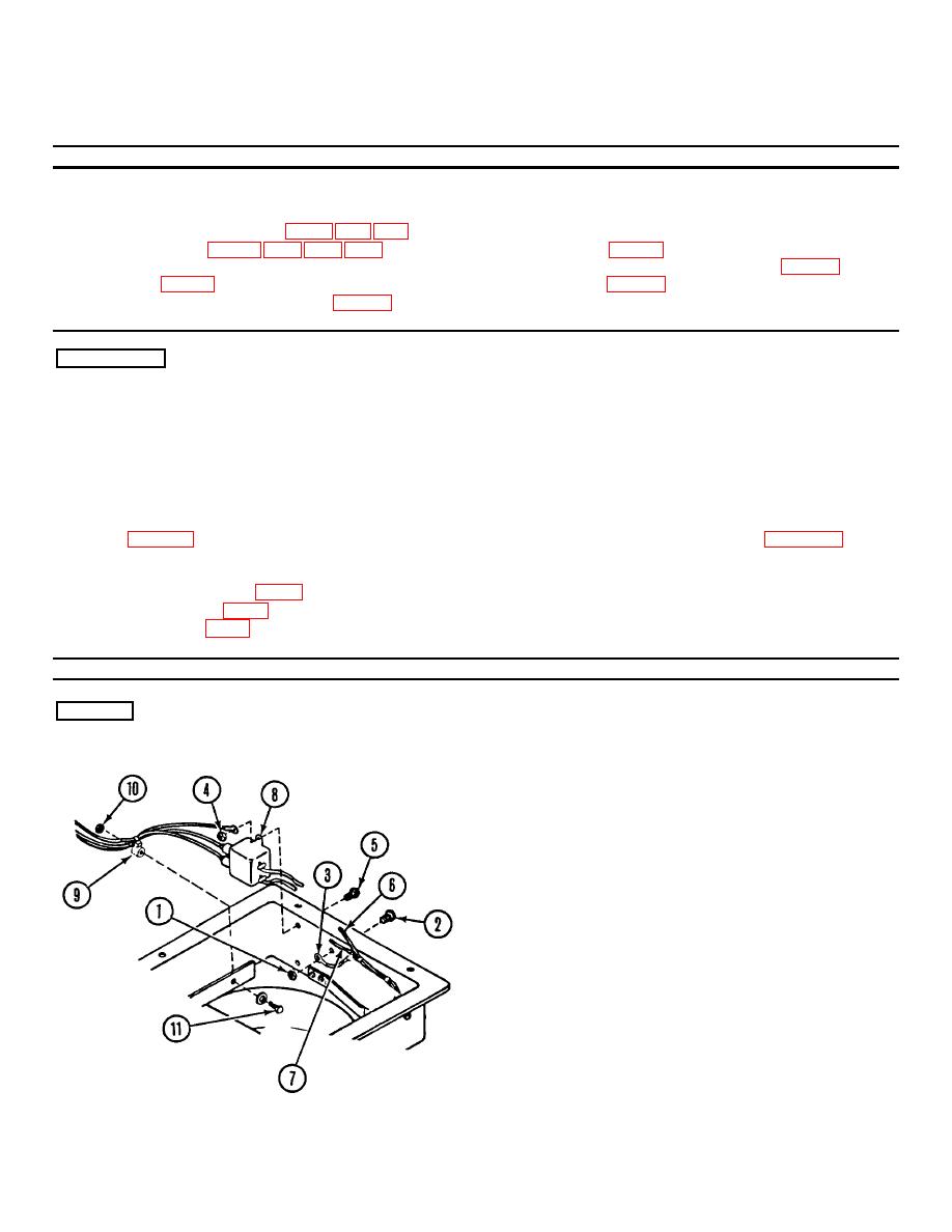
Remove nut (1) and screw (2) from GRD 4
terminal lug (3).
2.
Remove two nuts (4) and screws (5).
3.
Tag and unsolder wires (6 and 7) from RFI
filter FL2 (8).
4.
Cut tiedown strap (9). Remove nut (10), screw
(11) and tiedown strap (9).
2-9
|
|
Privacy Statement - Press Release - Copyright Information. - Contact Us |