 |
|||
|
|
|||
|
|
|||
| ||||||||||
|
|
 TM 3-4240-302-30&P-6
2-7. AIRFLOW VALVE (CONT).
LOCATION
ITEM
ACTION
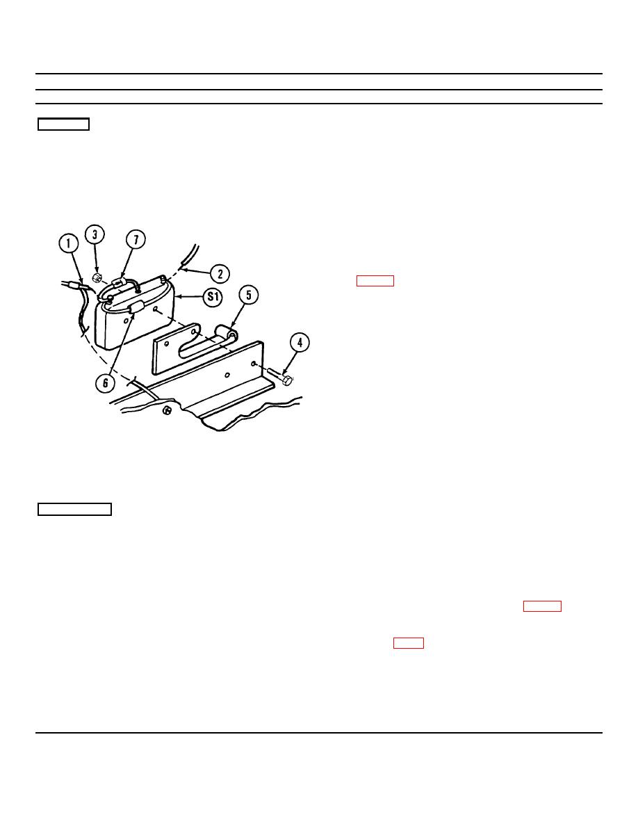
REMOVAL
Airflow Valve
S1 sensitive switch and
1.
Tag and unsolder wire (1) from normally
adapter
closed (NC) terminal on switch (51).
2.
Tag and unsolder wire (2) from common (C)
terminal on switch (S1).
3.
Remove two nuts (3) and screws (4).
4.
Remove switch (S1) and adapter (5).
5.
Remove and retain capacitor (6) and diode (7)
INSTALLATION
1.
Install S1 sensitive switch and adapter (5) using
two screws (4) and nuts (3).
2.
Solder wire (1) to normally closed (NC)
terminal of S1 sensitive switch.
3.
Reinstall diode (7) and capacitor (6) (p. 2-15).
4.
Coat electrical connections with oil varnish
(item 3, app C).
2-16
|
|
Privacy Statement - Press Release - Copyright Information. - Contact Us |
|
|
Integrated Publishing, Inc. - A (SDVOSB) Service Disabled Veteran Owned Small Business
|

