 |
|||
|
|
|||
|
|
|||
| ||||||||||
|
|
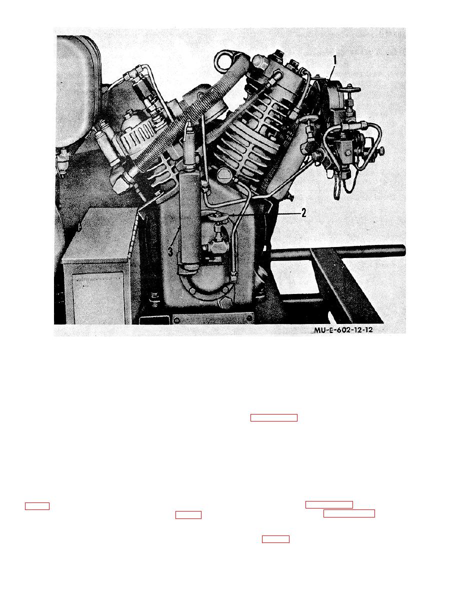
 1
Charging manifold bleeder valve
2
Bleeder valve
8
Aftercooler condensate leg
Figure 12. M1A1 compressor, side view.
valve. Open the bleeder valve on the section of the
WARNING
manifold to which the charging line is connected.
Operating personnel must always
position themselves away from the
d. After-Charging Procedure. Follow the directions
charging hose assembly during
charging operations. If either the
charging hose or connector fail, the
12. Using Commercial Air Cylinder
remaining portion of the charging
hose will "whip around" and may
WARNING
injure personnel in its path.
Do not use a commercial air cylinder
(2) Close the bleeder valve (1 or 2, fig.12) on
if its markings are missing or
the side of the manifold to which the charging line is
defaced.
attached.
(3) Open the high-pressure sphere valve (2,
volume and pressure. Paragraph 7b gives cylinder
(4) Observe the pressure gage (2, fig. 11) for
charging capacities.
the tank being charged. When the gage indicates 2,000
b. Apparatus. Use a 6-foot rubber hose assembly
psi,
close
the
high-pressure
sphere
(36, fig. 2), quick-coupling adapter assembly
18
|
|
Privacy Statement - Press Release - Copyright Information. - Contact Us |