 |
|||
|
|
|||
|
|
|||
| ||||||||||
|
|
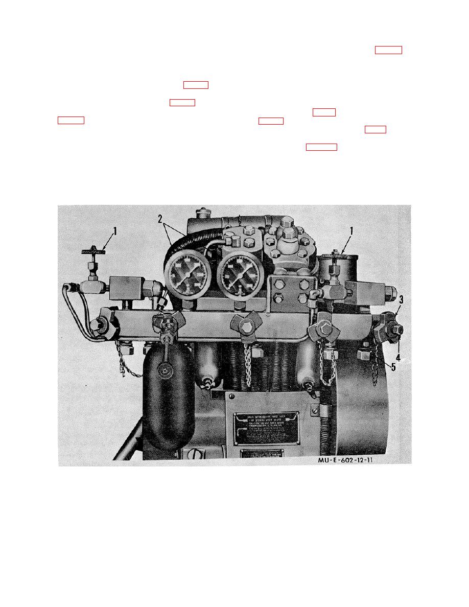 (3) Connect the pressure hose to the plug on the
that no pressure is indicated on the
high-pressure sphere valve.
manifold pressure gages (2, fig. 11) in
11. Using M1 A1 Compressor
that section.
Charge the ABC-M9-7 or M9A1-7 flamethrower high-
(3) Remove the manifold machine plug (4) from the
pressure sphere as follows:
hammer lug locknut (3).
a. Attaching Hose Assembly
(36, fig. 2) to
(4) Unscrew the charging line adapter (5) from the
Compressor.
manifold and screw it into the hammer lug locknut (3).
(1) Close the manifold intake valve (1, fig. 11) on the
(5) Screw the adapter that is on the 6- foot rubber
unused side of the' charging manifold. Close the bleeder
hose assembly (36, fig. 2) into the charging line adapter
valve (2, fig. 12) that is in the aftercooler condensate leg
(5, fig. 11). Tighten the hammer lug locknut.
(3).
b. Attaching Charging Hose (18, fig. 2) to High-
(2) Leave the charging manifold bleeder valves (1)
Pressure Sphere. Attach the charging line to the high-
in the open position.
pressure sphere (para 10b).
WARNING
c. Charging.
Before
removing
the
manifold
(1) Start the compressor engine (TM 3- 1040-203-
12)
machine plug, see that the manifold
bleeder valve of the section in use is
open.
Insure
1
Manifold intake valves
3 Hammer lug locknut
5 Charging line adapter
2
Pressure gages
4 Manifold machine plug
Figure 11. Charging manifold section of M1A1compressor.
17
|
|
Privacy Statement - Press Release - Copyright Information. - Contact Us |
