 |
|||
|
|
|||
|
Page Title:
Section III. MAINTENANCE PROCEDURES |
|
||
| ||||||||||
|
|
 TM 3-4240-302-30&P-1
Section III. MAINTENANCE PROCEDURES
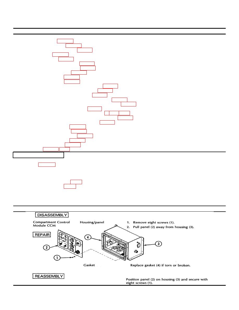
2-7. COMPARTMENT CONTROL MODULE.
This task covers the removal, disassembly, repair, reassembly and installation of the following:
a. Housing/panel (p. 2-77)
b. Pressure switch S6 (p. 2-78)
c. Pressure transmitter MT2 (p. 2-79)
d. Loop clamp (p. 2-80)
e. Power card A1 (p. 2-81)
f.
Batteries (warning system) (p. 2-81)
g. Printed circuit assembly A4 (p. 2-82)
h. Thermal flasher DS12 (p. 2-83)
i.
Switching card A2 (p. 2-84)
j.
Warning horn LS1 (p. 2-85)
k. DUST FAN DEFECT indicator light DS7 (p. 2-86)
I.
CHANGE FILTER indicator light DS8 (p. 2-87)
m. INDICATORS circuit breaker CB5 (p. 2-88)
n. ENTRANCE PRESSURE circuit breaker CB6 (p. 2-89)
o. COMPARTMENT PRESSURE circuit breaker CB8 (p. 2-90)
p. MAIN FAN circuit breaker CB7 (p. 2-91)
r.
LOW PRESSURE switch/indicator light S11/DS9 (p. 2-93)
s. MASK switch/indicator light S10/DS11 (p. 2-93)
t.
Diodes CR4 and CR5 (p. 2-94)
u. HORN OFF switch K2 (p. 2-95)
v. POWER toggle switch S9 (p. 2-96)
w. Female hose adapter (p. 2-97)
x. Male hose adapter (p. 2-98)
INITIAL SETUP
Troubleshooting References
Refer to page 2-3
Equipment Condition
Compartment control module removed from shelter
Materials/Parts
Insulation sleeving (item 1, app C)
Lacing - Tape (item 2, app C)
Tools
Electronic Equipment Tool Kit TK-105/G
References
TB SIG 222
LOCATION
ITEM
ACTION
2-77
|
|
Privacy Statement - Press Release - Copyright Information. - Contact Us |
