 |
|||
|
|
|||
|
|
|||
| ||||||||||
|
|
 TM 3-4240-302-30&P-1
2-7. COMPARTMENT CONTROL MODULE (CONT).
LOCATION
ITEM
ACTION
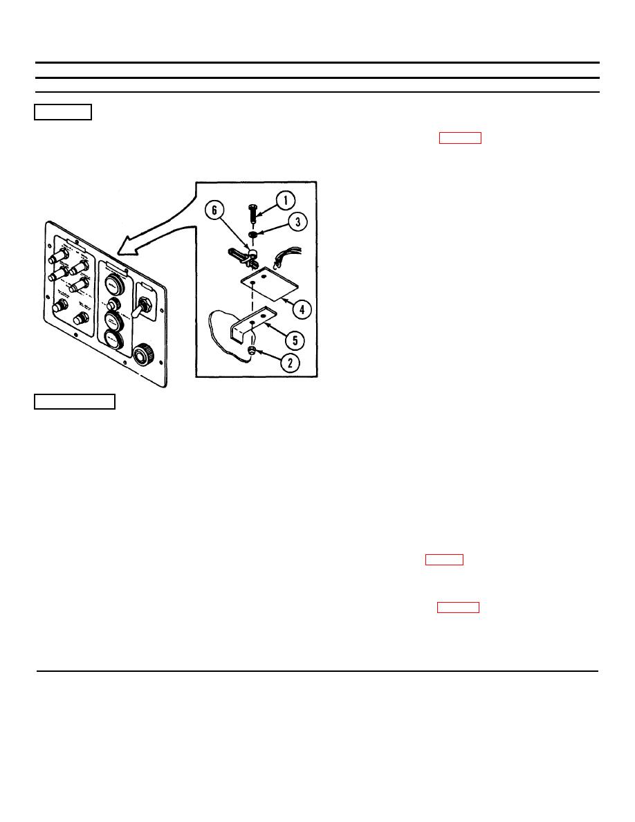
REMOVAL
Panel
Printed circuit board A4
1. Disassemble CCM (p. 2-77).
2. Remove two screws (1), nuts (2), and washers (3).
3. Unsolder and tag wires and remove printed
circuit board A4 (4).
INSTALLATION
CAUTION
Apply heat sink pliers to leads of diodes when
soldering terminals. This action prevents heat
damage. This action prevents heat damage.
Use care to apply only enough heat to form a
good solder joint. This applies to all terminals.
1. Connect and solder wires to auxiliary
switching printed circuit board A4 (4). Refer to
wiring diagram (p. 2-99).
2. Place printed circuit board A4 (4) on bracket
(5) and attach using screws (1), washers (3),
cable strap (6), and nuts (2).
3. Reassemble CCM (p. 2-77).
2-82
|
|
Privacy Statement - Press Release - Copyright Information. - Contact Us |
