 |
|||
|
|
|||
|
|
|||
| ||||||||||
|
|
 TM 3-4240-302-30&P-1
2-7. COMPARTMENT CONTROL MODULE (CONT).
LOCATION
ITEM
ACTION
REMOVAL
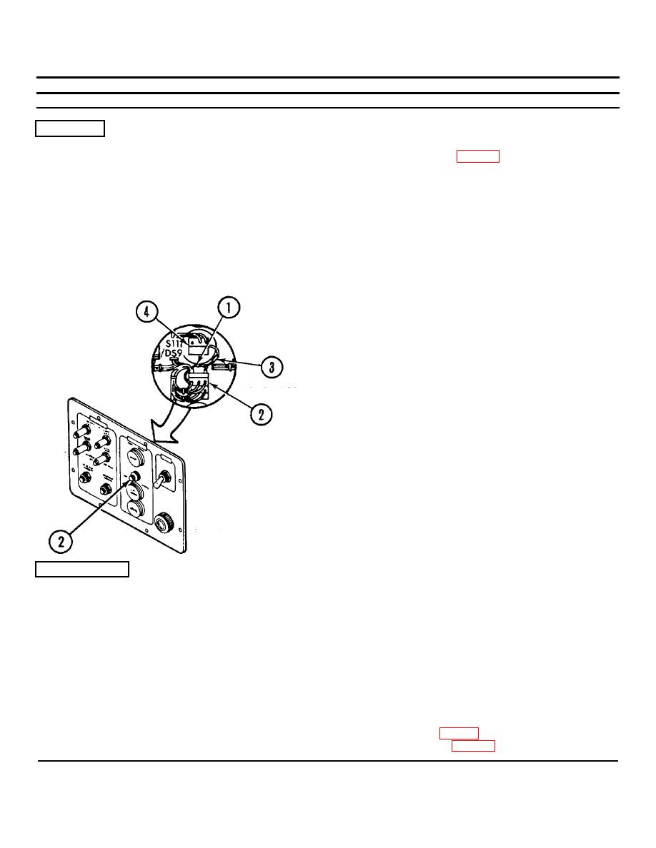
HORN OFF switch K2
Diodes CR4 and CR5
1. Disassemble CCM (p. 2-77).
CAUTION
Apply heat sink pliers to leads of diodes
when unsoldering. Excessive heat will
damage the diodes.
2. Unsolder diode CR4 (1) from HORN OFF
switch K2 (2).
3. Unsolder diode CR5 (3) connected between
HORN OFF switch K2 (2) and DS9 (4).
INSTALLATION|
CAUTION
Diodes must be connected properly or
damage to circuitry will result. Observe
the banded end of the diodes.
CAUTION
Apply heat sink pliers to leads of diodes
when soldering. Excessive heat will
damage the diodes.
1. Solder diodes CR4 (1) and CR5 (3). Refer to
wiring diagram (p. 2-99).
2. Reassemble CCM (p. 2-77).
2-94
|
|
Privacy Statement - Press Release - Copyright Information. - Contact Us |
