 |
|||
|
|
|||
|
|
|||
| ||||||||||
|
|
 general check to indicate the equipment which probably
14. Connections
has been shipped.
d. Check the overall equipment for any loss or
Determine the voltage, type of current available, and
damage that might have occurred during shipment. If
the type of enlarger to be used (par. 4). Check to see
the equipment has been damaged or is incomplete, refer
that all switches are in the OFF position. See that the
to paragraph 2.
corrective voltage lamps (110-volt or 6-volt) are in the
e. If the equipment has been used or
safelight and in the enlarger body. If the lamp must be
reconditioned, check to see whether it has been changed
changed, refer to paragraph 36a.
by a modification work order (MWO). If modified, the
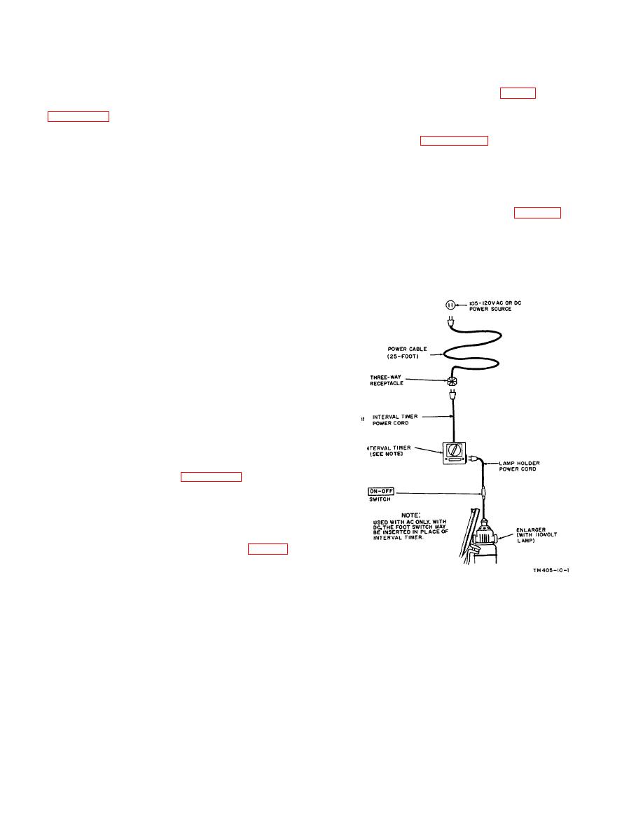
a. PH-129, PH-129-B, or EN-16 (1). Connect the
MWO number will be marked on the front of the enlarger
power cable (25-foot) to a 105- to 120-volt ac or dc
body.
power source. Connect the remainder of the equipment
12. Siting
as follows:
(1) If the power source is ac, connect the
equipment as shown in figure 11.
a. Exterior Requirements. The site where the
(2) If the power source is dc, replace the
processing set will be located is governed by the tactical
interval timer with a foot switch.
situation and by the type of housing facilities available
b. PH-129-A or PH-639(*)/TF. The procedure for
(tents, buildings, etc.). If possible, choose a location
connecting the PH-129-A or the PH639(*)/TF to an ac
where a fiat area is available for setting up the
power source is covered in (1) below. The procedure for
equipment.
Be sure that drainage facilities are
connecting to a dc power source is covered in (2) below.
adequate.
(1) General. After locating the shelter in
which the processing set is to be placed,
make the necessary arrangements for
darkroom operation. Equip all windows
with material to prevent the passage of
light. Shelters should be light tight.
Note.
Refer to TM 11-401 for details of shelter
(darkroom)
requirements.
(2) Space
Requirements.
Operating
personnel must have sufficient space and
table area to allow the work of developing
and printing.
The minimum space
required is 8 by 8 by 8 feet.
(3) Electrical requirements. For the power
requirements of the enlarger and the
safelight refer to paragraph 4.
(4) Water requirements. Large quantities of
fresh water (running water for 8 to 12
changes) are needed for washing prints
and negatives.
13. Assembly and Installation The processing set
must be assembled and installed on the site (par. 12) at
which it is to be operated. At this time arrangements
should be made to secure the services of organizational
maintenance personnel for assembly and installation of
the equipment.
TM405-10-1
Figure 11. Connection diagram for 105- to 120-volt ac or
dc of PH-129, PH-1 29-B, or EN-16(1).
AGO 5894A
17
|
|
Privacy Statement - Press Release - Copyright Information. - Contact Us |
