 |
|||
|
|
|||
|
Page Title:
Ac connections (fig. 12). For 110-volt ac |
|
||
| ||||||||||
|
|
 TM405-10-2
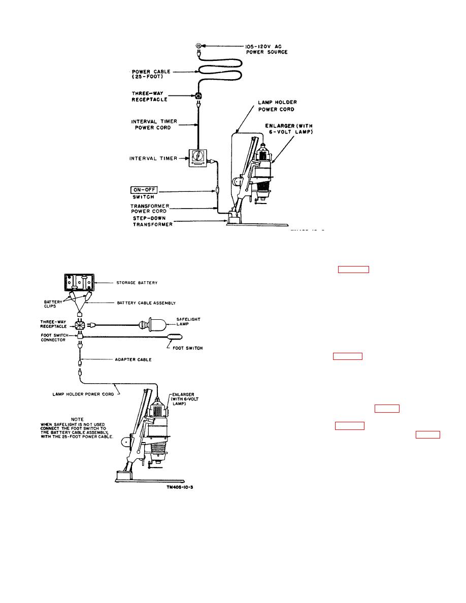
Figure 12. Connection diagram for 105- to 120-volt ac of PH-129-A or PH-639(*)!TF.
(1) Ac connections (fig. 12). For 110-volt ac
operation proceed as follows:
(a) Connect the lamp holder power cord to the
stepdown transformer.
(b) Connect the transformer power cord to the
interval timer.
(c) Connect the interval timer power cord to
the three-way receptacle.
(d) Connect the 25-foot power cable to the
power source.
(2) Dc connections (fig. 13). For 6- to 8volt dc
operation, using a storage battery power source,
proceed as follows: Note. The PH-129-A or the
PH-639(*)/ TF is to be operated from a storage
battery power source only under emergency
conditions. Check to see that the correct type of
storage battery is being used (par. 8).
(a) Check to see that a 6-volt safelight lamp is
being used (par. 36a).
(b) Connect the equipment as shown in figure
13.
TM405-10-3
Figure 13.. Connection diagram for 8- to 8-volt do of PH-
12D-A or PH-40(*) /TF.
AGO 5894A
18
|
|
Privacy Statement - Press Release - Copyright Information. - Contact Us |