 |
|||
|
|
|||
|
Page Title:
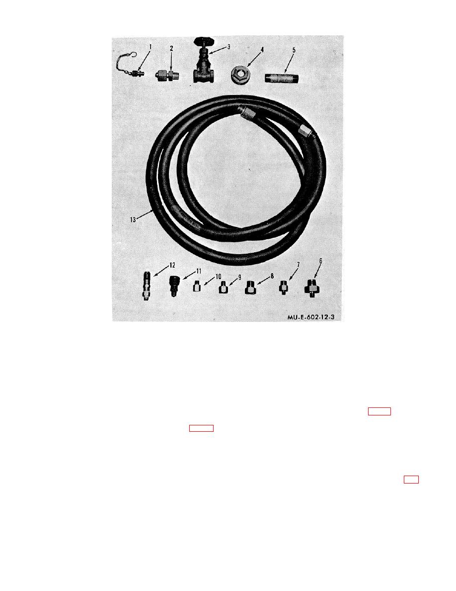
Figure 3. Hose assembly, adapters, tube reducers, and valves. |
|
||
| ||||||||||
|
|
 1
Check valve assembly
5
Pipe nipple
10
Adapter (pipe to tube)
2
Pressure regulator adapter
6
Adapter (pipe to tube)
11
Quick-disconnect coupling half
3
Gate valve
7
Tube reducer
12
Quick-coupling adapter assembly
4
Pipe bushing
8
Tube reducer
13
Rubber hose
9
Tube reducer
Figure 3. Hose assembly, adapters, tube reducers, and valves.
j. Compressed Air Pressure Regulator.
adapter (29), and a preformed packing (30).
The
The test gage assembly (31) is used to test the pressure
compressed air pressure regulator (12, fig. 4) consists of
regulator on the ABC-M9-7 or M9A1-7 flamethrower.
a pressure gage (6), which is scaled from zero to 60 psi,
i. Hose Assembly. The hose assembly (fig. 3)
a cylinder connection nut (7), a cylinder connection gland
consists of a 15-foot rubber hose (13) with male fittings
(8), an outlet connection adapter (9), a pressure
on each end, a nonrising-stem gate valve (3), a pipe
regulator (10), and an adjusting screw (11).
The
bushing (4), and a pipe nipple (5). The hose assembly is
compressed air pressure regulator is used to regulate
used to transfer fuel from a 55-gallon drum to the fuel
and reduce pressure from the pressure source to the
tanks of portable flamethrowers.
pressure required for flame-fuel-filling operations.
k. Hose Assembly. The hose assembly (13, fig.
6
|
|
Privacy Statement - Press Release - Copyright Information. - Contact Us |
