 |
|||
|
|
|||
|
Page Title:
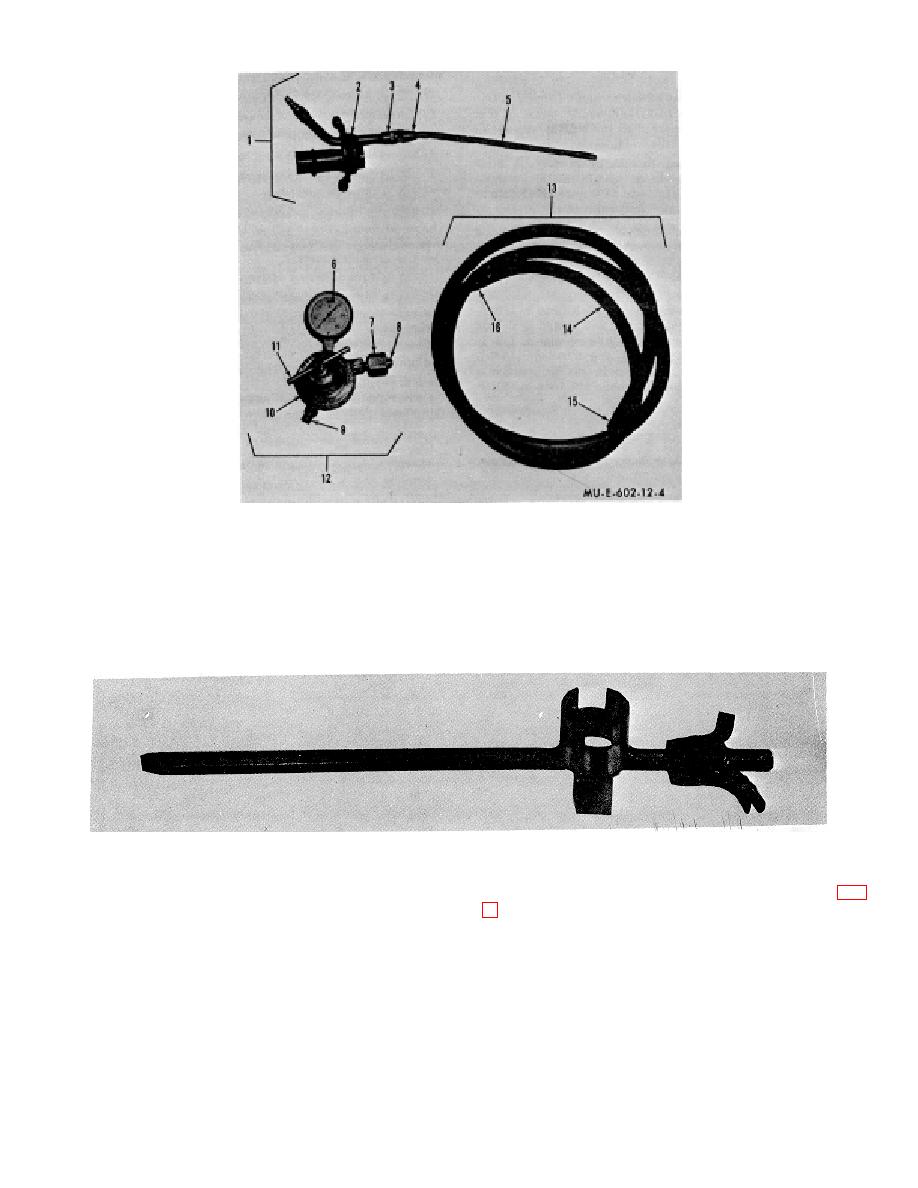
Figure 4. Pressure regulator, fuel transfer cap, and hose assembly. |
|
||
| ||||||||||
|
|
 1
Fuel transfer cap
7
Nut
12
Compressed air pressure
2
Filling plug assembly
8
Gland
regulator
3
Tube fitting
9
Outlet connection adapter
13
Hose assembly
4
Coupling
10
Pressure regulator
14
Hose
5
Tube
11
Adjusting screw
15
Female fittings
6
Pressure gage
16
Clamps
Figure 4. Pressure regulator, fuel transfer cap, and hose assembly.
Figure 5. Bung wrench.
l. Fuel Transfer Cap. The fuel transfer cap (1, fig.
4) consists of an 8-foot rubber hose (14), two female
fittings (15), and two clamps (16). The hose assembly is
used to transfer pressure from the compressed air
fitting (3). A brass coupling (5) attaches the tube fitting
pressure regulator to a 55- gallon drum or 5-gallon
(3) to a copper tube (5). The fuel transfer cap is used
gasoline can during flame-fuel filling of a portable
with a pressure source to transfer fuel from a
flamethrower.
7
|
|
Privacy Statement - Press Release - Copyright Information. - Contact Us |
