 |
|||
|
|
|||
|
Page Title:
Attaching Charging Line to Pressure Tank. |
|
||
| ||||||||||
|
|
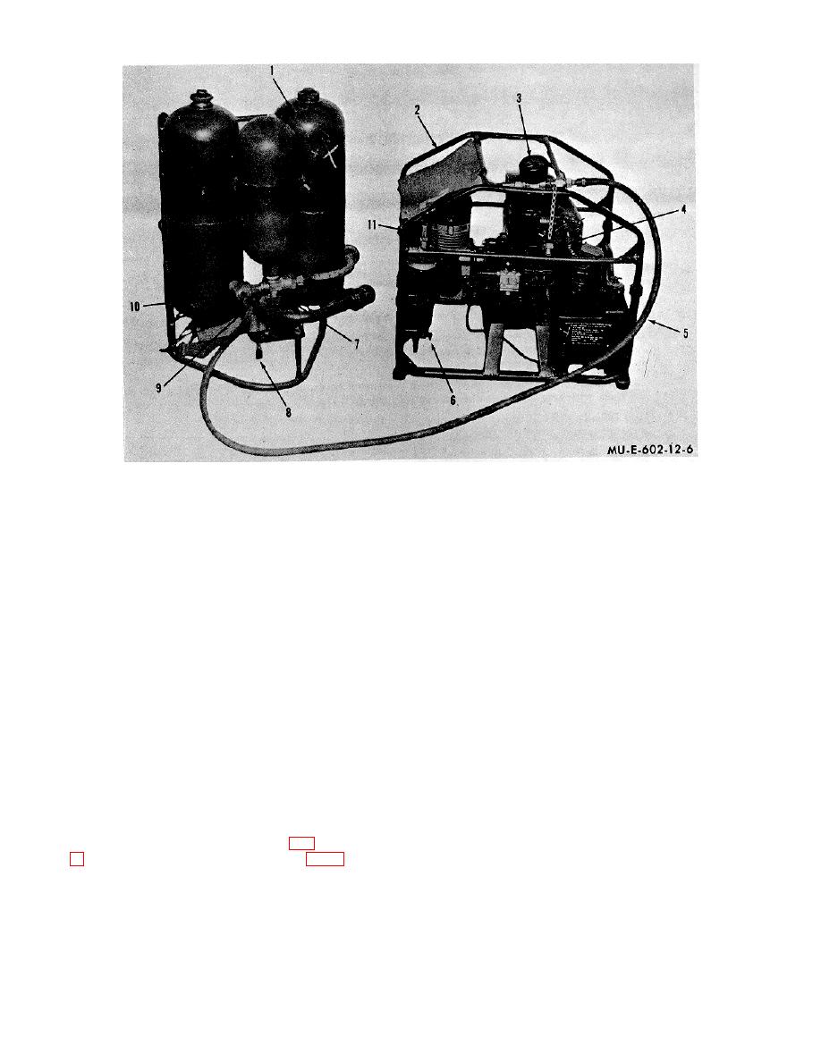 1
M2A1-7 flamethrower
5
Hose
9 Check valve
2
AN-M4 compressor
6
Globe valve
10 Bleeder valve
3
Pressure gage
7
Pressure tank valve
11 Charging hose assembly
4
Safety plug
8
Check valve cap
Figure 6. Charging M2A1-7 flamethrower with AN-M4 compressor.
b. Attaching Charging Line to Pressure Tank.
c. Charging.
(1) Open the globe valve (6) that is on the separator
of the AN-M4 compressor.
WARNING
NOTE
Operating personnel must always
Opening the globe valve prevents
position themselves away from the
pressure buildup during starting and
charging hose assembly during
relieves the starting load on the
charging opera- tions. If either the
engine.
charging hose or connector fail, the
remaining portion of the charging
(2) Start the engine.
hose will "whip around" and may
NOTE
injure personnel in its path.
There are four models of the AN-M4
compressor.
Refer to applicable
(1) Close the pressure tank value (7) on the M2A1-7
technical manual (appendix) for the
flamethrower (1).
type of compressor being used.
(2) Unscrew the check valve cap (8) from the check
value (9).
(3) Close the globe valve.
(3) Connect the valve assembly (34, fig.
(4) During charging, check the pressure gage (3) to
make sure that the pressure is increasing at a uniform
check valve.
rate.
(4) Close the bleeder valve (10).
10
|
|
Privacy Statement - Press Release - Copyright Information. - Contact Us |
