 |
|||
|
|
|||
|
|
|||
| ||||||||||
|
|
 TM 11-6665-232-40
be overlooked. If present, this type of trouble
ate (center) position. The pointer of the meter
often may be made to appear by tapping or jar-
should return to 0.
ring the equipment. Check the wiring (fig. 3-5
and 3-6) and connections within the radiacme-
mined that the radiacmeter is operating nor-
ter.
mally (b above), install the radiacmeter in the
(6) Calibration check. A calibration check
AN/USM-2 and perform the calibration check
procedure as instructed in TM 11-6665-227-12.
obtained from the radiacmeter are accurate.
The radiacmeter is exposed to known dose rates
3-4. Troubleshooting Procedures
of radiation and the readings obtained are com-
pared with the known dose rates.
a. Genera/. The first step in servicing a defec-
tive readiacmeter is to localize the fault. Lo-
3-5. Troubleshooting Chart
calizing means tracing the fault to a defective
NOTE
stage or circuit responsible for the abnormal
To reach the parts of the radiacmeter,
condition. The second step is isolation. Isolation
r e m o v e the battery cover from the
means locating the defective part or parts. Some
radiacmeter (TM 11-6665-232-12), un-
faults, such as burned-out resistors, can often be
screw the small captive screws in the
located by sight and smell. The majority of the
cover assembly, and carefully remove
faults, however, must be located by checking
the cover assembly.
resistances.
a. General. In the troubleshooting chart (c be-
b. Localization. The tests listed below will aid
low), the procedures are outlined for localizing
in isolating the trouble. First localize the trou-
t r o u b l e s within the various sections of the
ble to a single circuit, and then isolate the trou-
radiacmeter. The parts locations are indicated
ble within that circuit by resistance; continuity,
in figures 3-1 through 3-4. Depending on the
and voltage measurements.
nature of the operational symptoms, one or
(1) Visual inspection. The purpose of visual
more of the localizing procedures will be neces-
inspection is to locate faults without testing or
sary. When trouble has been localized to a par-
measuring circuits. All meter readings or other
ticular portion of the radiacmeter, use voltage
visual signs should be observed and an attempt
and resistance measurements to isolate the
made to localize the fault to a particular circuit.
trouble to a particular part.
(2) Operational test. Operational tests fre-
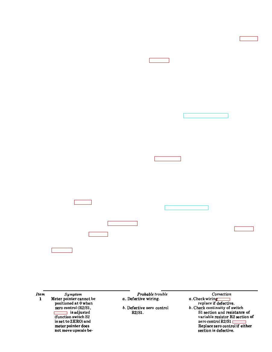
b. Use of Chart. The troubleshooting chart is
quently indicate the general location of trouble.
designated to supplement the troubleshooting
The calibration check (para 3-3) is a good opera-
chart in TM 11-6665-232-12. If previous opera-
tional test.
tional checks have resulted in reference to a
(3) Resistance measurements. The resis-
particular Item of this chart, go direct to the
tance measurements will help locate the indi-
referenced item. If no operational symptoms are
vidual component part at fault. Figures 3-1
known, perform the calibration check (para 3-3)
through 3-4 show the location of all components.
and proceed until a symptom appears.
Use the resistor color code (fig. FO-1) to find the
c. Troubleshooting Chart.
value of the components.
NOTE
(4) Troubleshooting chart. The troubleshoot-
Replacement of parts indicated and
ing chart (para 3-5) lists symptoms of common
calibration of radiacmeter can be per-
troubles and gives (or references) corrective
formed only by depot repairmen. If a
measures.
component is replaced, the radiacmeter
(5) Intermittent trouble. In all the tests, the
must be recalibrated.
possibility of intermittent troubles should not
|
|
Privacy Statement - Press Release - Copyright Information. - Contact Us |