 |
|||
|
|
|||
|
Page Title:
CHAPTER 2 FUNCTIONING OF EQUIPMENT |
|
||
| ||||||||||
|
|
 TM
11-6665-232-40
FUNCTIONING OF EQUIPMENT
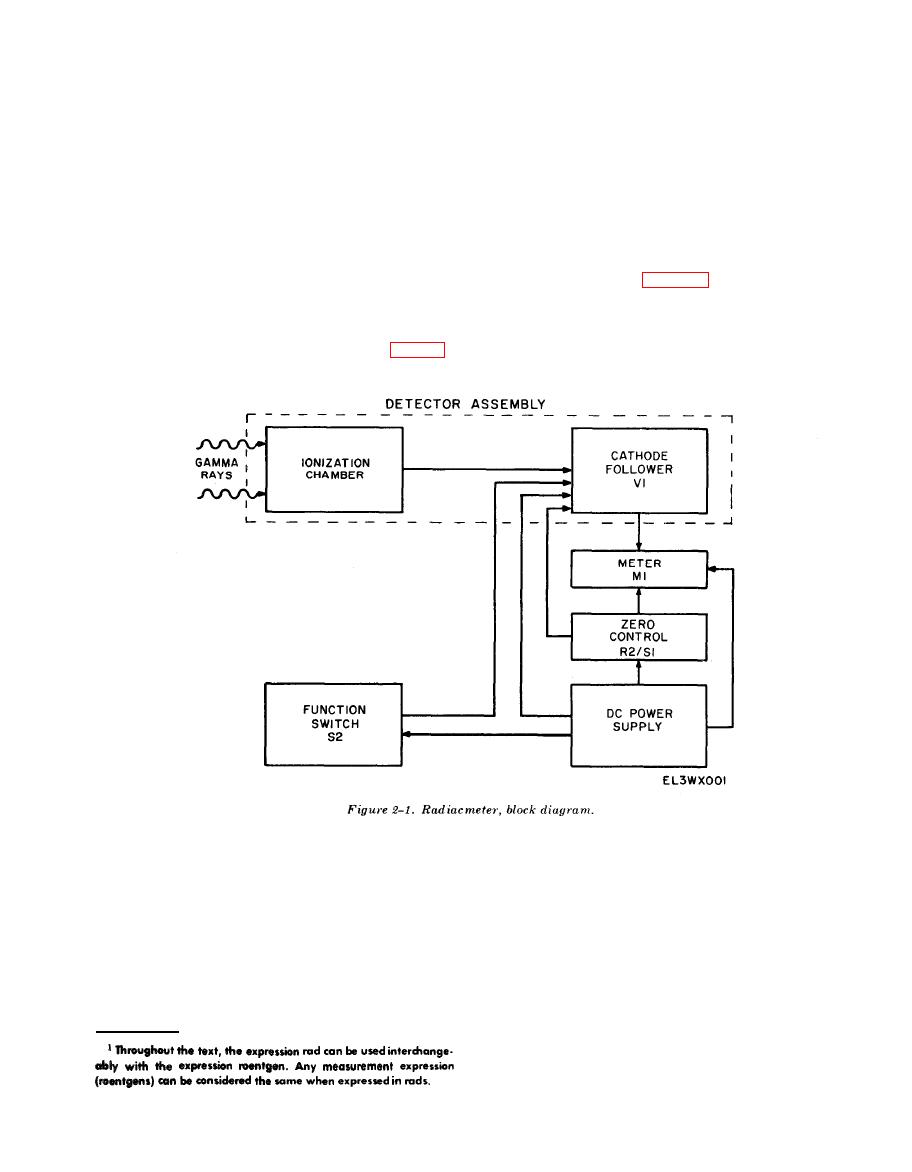
a. The radiacmeter block diagram consists of
the six blocks as shown in figure 2-1. The ioniza-
Radiacmeter IM-174A/PD is a portable, tactical
tion chamber and the cathode follower VI are
survey meter which is used to detect gamma
physically contained in the detector assembly.
radiation dose rates of from 1 to 500 roentgens
Four other blocks include the meter, zero con-
trol, dc power supply, and the function switch
of the radiacmeter is discussed below.
S2.
b. When the radiacmeter is in operation,
meter will indicate the strength of the gamma
rays in the ionization chamber.
gamma rays pass through the radiacmeter case
c. Zero control R2/S1 provides on/off control
and enter the ionization chamber which func-
of the radiacmeter and zero adjustment. Zero
tions as a gamma ray detector. The gamma rays
adjustment is accomplished in conjunction with
cause a small amount of current to flow through
function switch S2. When S2 is placed in the
a large value resistor in the grid circuit of V1
ZERO position the ionization chamber is re-
producing a positive voltage as input to V1. Cur-
moved from the cathode follower and the zero
rent increases through V1 and through meter
control is then adjusted to balance the circuit so
M1 in the cathode circuit of VI. Meter Ml is
that no current flows through the meter and it
calibrated in rad/hr so that current through the
indicates zero.
d. Function switch S2 also provides a means
to check the radiacmeter's operation. When S2 is
set to CHECK the ionization chamber is again
|
|
Privacy Statement - Press Release - Copyright Information. - Contact Us |
