 |
|||
|
|
|||
|
|
|||
| ||||||||||
|
|
 TM
11-6665-232-40
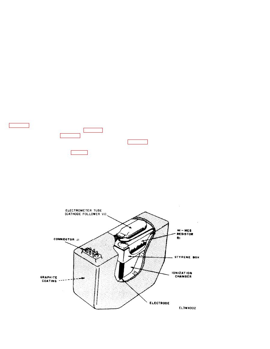
with a non flaking colloidal graphite to provide
removed from the circuit and a fixed, positive
the proper electrical characteristics. The elec-
bias is applied to cathode follower V1 and the
meter responds by indicating in the check band
trode is insulated from the walls of the ioniza
tion chamber.
on the meter scale,
b. The IM174A/PD has a response which var-
22. Circuit Analysis
ies nonlinearly with radiation intensity, so that
There are two versions of the IM174A/PD in
the dose rate range of 1 to 500 rad/hr can be
use; one, which uses a single battery (single bat-
measured without the necessity of range switch-
tery type) to operate a dc power supply for the
ing. This is done by the use of a nonlinear
different operating voltages required, and; the
ionization chamber with a linear amplifier. Non-
second version that uses six separate batteries
linear response in an ionization chamber will
(multi-battery type) for supplying the de operat-
result if the collection voltage is kept low, so
ing voltages to the radiacmeter, Both versions
that a fraction of the ions produced in the ioni-
use the same detector assemblies, but the other
zation chamber will recombine before they are
circuits which operate the meter, zero control,
collected. The fraction that recombines is a
function switch, and the dc power supply are
function of the ion concentration in the ioniza-
connected differently and have different
tion chamber. The effect of operating the ioniza-
schematics. Except for the detector assembly
tion chamber in this condition is to produce an
o u t p u t current which varies approximately
below for the single battery type (para 25) and
]ogarithmically with the radiation dose rate.
the multi-battery type (para 2-4) radiacmeters.
c. On the schematic for the detector, assembly
23. Detector Assembly
its conductive coating is shown around the elec-
trode used for collecting the ions from gamma
a. The detector assembly (fig. 2-2) is made of
ray penetration of the ionization chamber. The
cast epoxide resin and is hermetically sealed. It
consists of an air filled ionization chamber; an
electrode is connected to the grid, pin 6, of V1.
electrode; and an electrometer tube (cathode-
Other connections to the detector assembly
through connector J1 are: Pin C which supplies
follower V1) and high megohm resistor R1, both
plate voltage; pins A and I) supply filament
mounted in a styrene box; and a connector (J1).
The inside of the ionization chamber is coated
power and cathode connection; pin F provides
|
|
Privacy Statement - Press Release - Copyright Information. - Contact Us |
