 |
|||
|
|
|||
|
Page Title:
Section IV. TROUBLESHOOTING PERMANENTLY CONNECTED CIRCUITS AND EQUIPMENT |
|
||
| ||||||||||
|
|
 TM 11-5895-878-14&P
NOTE
(b) Special tests on circuits or equipment.
Refer to site cable run drawings for
(c) Changes in frequency assignments.
IDF to equipment cabling details.
(10) Advise the CCO, SCCO, or ICO when:
b. Change cross-connection or make new
(a) Any circuit has been restored or rerouted
connections on the associated IDF's (paras 2-3 through
over new facilities and must be tested from end-to-end.
(b) A service will not be able to start on date
cable or VFCT assignments as necessary.
and time specified in the TSO.
c. Record cross-connections on circuit record card.
d. Perform the necessary in-house equipment
4-12. Procedure for Changing and Building Circuits
tests.
a. Patch around the in-house portion of the
e. Remove patches or plugs installed in (a) above.
existing circuit (fig. 3-4), or terminate the circuit legs on
f. Perform the necessary QA station-to-station
the line side of the patch panels with 600 ohm terminal
tests (para 3-20).
plugs.
Section IV. TROUBLESHOOTING PERMANENTLY CONNECTED CIRCUITS AND EQUIPMENT
refer to the "Trouble Symptom" column in the chart.
4-13. Use of Troubleshooting Charts
Perform the checks and corrective measures indicated
Troubleshooting of this facility is based upon
in the "Check and Corrective Maintenance" column to
malfunctions that may occur during normal operation of
locate and clear the trouble.
the equipment in the system. When a trouble occurs,
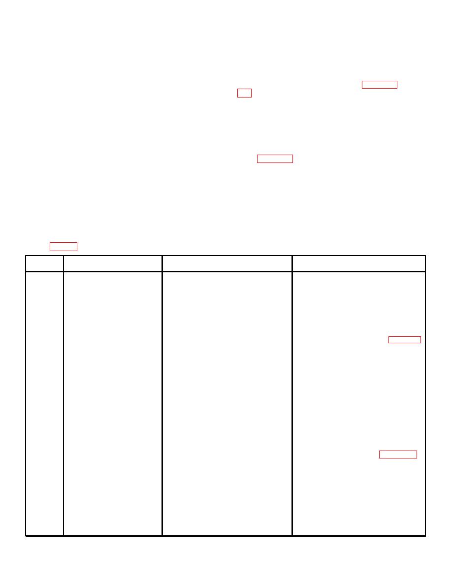
4-14. Troubleshooting Chart, Major/Minor Alarm Panel
Item
Trouble Symptom
Probable trouble
Check and corrective maintenance
1
No audible tone from audible
a. Tellite has been depressed, locking
a. Check for trouble as indicated by
alarm panel with a Tellite
out audible tone.
Tellite.
b. Gnd from alarm panel not being ex-
b. Remove the appropriate cross-connect.
tended to audible alarm panel.
from IDF and check for ground from
alarm panel output on the IDF block.
(1) If ground is found, check for -48 vdc
on the audible alarm input lead. If
battery is not present replace the
patch and check the operation of
the audible alarm panel (para 4-17).
(2) If no ground is found, remove the
connector from rear of alarm panel.
Make a continuity check from pin 91
of the connector (cable end) to the
IDF. After check is satisfactorily
completed, replace the cross-
connection patch cord.
c. Gnd not being extended through
c. If no ground is found on pin 91 it will
alarm panel.
be necessary to remove the alarm
panel from the bay to allow access
to the component parts. With the
top and bottom covers removed
make a continuity check, using a
VOM TS-352 or equal, from the pin
number that corresponds to the
illuminated lamp to Tellite pins NC1
and COM1. Refer to appendix D,
symbol number SW3, for Tellite
location. If continuity is obtained on
COM1 but not NC1 this indicates a
defective Tellite.
NOTE Care must be taken to
ensure that the (+) lead of the VOM
is connected to the corresponding
pin 1-45. This will forward bias the
diode in the circuit thus ensuring a
valid VOM reading.
4-5
|
|
Privacy Statement - Press Release - Copyright Information. - Contact Us |