 |
|||
|
|
|||
|
Page Title:
Station Clock Isolation Circuit |
|
||
| ||||||||||
|
|
 TM 11-5895-878-14&P
module A, panel 1 to jacks 1 and 2, row 5, module A,
panel 2 connects the data inhibit line to the T lead of the
patch panel control jack set. The T lead is connected
normal-through the jack sets tips to the T1 lead. The T1
lead is cabled to jack 1, row 6, of module A in panel 2.
The data inhibit return is completed to jack 2, row 6 of
module A in panel 2 by a common tie point connection.
(2) Patch cord No. 16, from jacks 1 and 2,
row 6, module A, panel 2 to jacks 3 and 4, row 2,
module A, panel 8 completes the data inhibit circuit to
the local equipment.
(3) Patch cord No. 17, from jacks 5 and 6,
row 2, module A, panel 8 to jacks 3 and 4, row 6,
module A, panel 2 connects the synchronize initiate lead
to the R1 lead of the patch panel jack set. The R1 lead
is connected normal-through jack sets rings to the R
lead. The R lead is cabled to jack 3, row 5 of module A
in panel 2. The synchronize initiate return is completed
to jack 4, row 5 of module A in panel 2 by a common tie
point connection.
(4) Patch cord No. 14, from jacks 3 and 4,
row 5, module A, panel 2 to jacks 5 and 6, row 2,
module A, panel 1 completes the synchronize initiate
circuit to the line equipment.
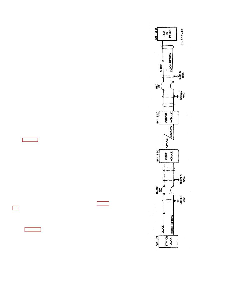
2-9. Station Clock Isolation Circuit
a. The station clock outputs are cabled to the black
IDF. When timing signals from the station clock must
be used in a red circuit, isolation between the red circuit
and the black IDF is required.
b. Isolation is accomplished by cross-connecting
the clock to a digital line isolator input module (located
in bay 2.20). The digital line isolators output module is
crossconnected to the red circuit at the red IDF.
c. One way optical coupling prevents anything
from being fed from the red circuit back to the station
clock.
2-10. Universal Digital Patch Panel
that is associated with each jack set. There are three
rows of identification (ID) card holders. The card
holders allow the circuit and equipment connected to the
circuit to easily be identified. The rear of each patch
panel (fig. 2-19), has two connectors (C1 and C2), that
are used to connect the jack set circuits (through
connectors J1 and J2) to the IDF.
Figure 2-17. Digital Line Isolators, Wiring Diagram
2-20
|
|
Privacy Statement - Press Release - Copyright Information. - Contact Us |
