 |
|||
|
|
|||
|
Page Title:
DISCRIMINATOR (Unit A5-Fig. 7-3) |
|
||
| ||||||||||
|
|
 TM 11-6625-3017-14
a d. c. term, Vm, almost proportional to the repetition
3.5 I.F. AMPLIFIER (Unit A3-Fig. 7-2)
frequency. This d. c. is fed, in the SET FREQ positions
of the Function switch, directly to the meter which is
This board, in the narrow box alongside the local
arranged to indicate SET when the i. f. is correct.
oscillator and power unit, contains three amplifying
stages, each of two transistors, Q1 to Q6, the stages
The presence of any appreciable degree of carrier
being coupled via band pass filters. No limiting occurs in
shift when modulation is applied to the input signal will be
the amplifier, and linearity, frequency response and an
indicated by the meter in the SET FREQ positions; the
overall gain of 50 dB are stabilized by a negative
amount of shift may be measured with a counter at I. F.
feedback loop in each stage.
OUT provided that the gate time is long with respect to
the period of the modulating signal or is equal to an
The output of the i. f. amplifier is taken in parallel
integral number of periods.
paths to the Function switch, SB, and to the I. F. OUT
socket via resistor R1 where it is available for viewing on
3.7 DISCRIMINATOR (Unit A5-Fig. 7-3)
an oscilloscope or for counting to check carrier frequency
drift. Via SB1 F, the output is routed to the a. m.
The pulse counter type discriminator occupies the
Detector or, in the f. m. positions, to the limiter.
front half of the central compartment fitted beneath the
chassis, the rear half of this compartment being
occupied by the limiter. The overall operation of the
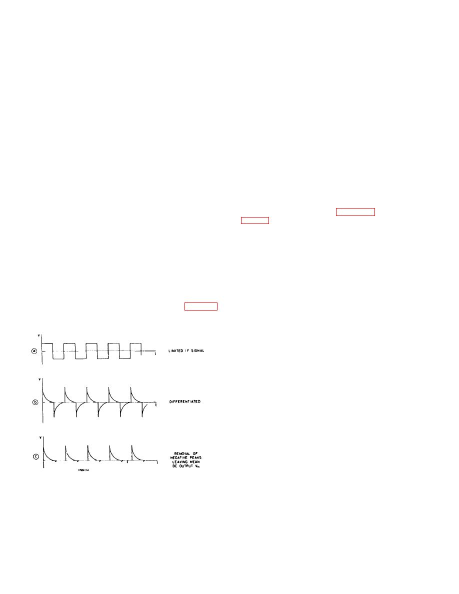
3.6 LIMITER (Unit A4 Fig. 7-3)
discriminator is described in section 3.1 and illustrated in
Housed in the rear half of a compartment
underneath the centre of the chassis, the limiter consists
The limiter output drives a Schmitt trigger circuit, Q2
of three stages of emitter-coupled amplifiers, arranged
and Q3, to produce a large square wave output into C4
so that signal amplitudes of either polarity above a
with constant rise and fall times. The collector voltage
certain level are limited. The emitters are connected to
of QI, the trigger amplifier, is set by RV1 so that the
balancing potentiometers to equalize the excursion in
Schmitt circuit is on the point of regeneration.
each direction.
The square wave is differentiated and passed to a
Part of the i. f. signal is tapped off from the third
pulse generator, Q4 and Q5, which produces positive-
stage, differentiated by C7 and LI and detected by MIl1 to
going pulses. These pulses are clipped b3 Q6. The
produce the uni-directional pulses shown in Fig. 3-3
emitter of this semiconductor is taken to the -12 V line,
(c).These pulses have
so that it clips the bases of the positive-going pulses,
thus maintaining constant amplitude.
Q7 is an emitter follower which, unlike Q6, is
conducting continuously and presents a constant low
impedance to the 200 kHz low-pass filter. The low
frequency change in the mean value of the pulses is
therefore passed and the i. f. signal rejected.
3.8 CALIBRATOR (Unit A12-Fig. 7-5)
Q1 and Q2 form a multivibrator running at nominally
4 kHz. CG, R8 and Q4 differentiate and clip the negative
spikes of the square wave output from Q2 and feed them
from a low impedance to the binary divider, Q7 and Q8.
Fig. 3-3. Operation of limiter
3-4
|
|
Privacy Statement - Press Release - Copyright Information. - Contact Us |
