 |
|||
|
|
|||
|
Page Title:
SECTION 3 TECHNICAL DESCRIPTION |
|
||
| ||||||||||
|
|
 TM 11-6625-3017-14
SECTION 3
TECHNICAL DESCRIPTION
This limited i. f. waveform is passed to the pulse
3.1 SYSTEM OPERATION
counter discriminator whose operation is illustrated in (c),
(d) and (e). A pulse of fixed amplitude and width is
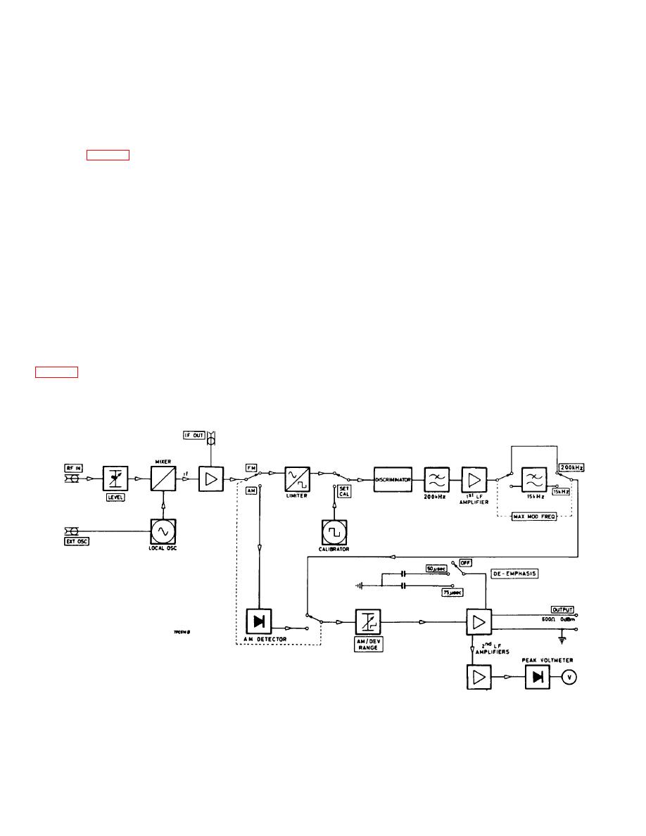
General operation of the TF 2300A Modulation
generated every time the clipped i. f. signal passes
Meter can be explained with reference to the block
through zero in the positive-going sense as shown in (b)
schematic, Fig. 3-1.
and (c). At any given repetition frequency, these pulses
have a constant mean amplitude, Vm, provided the pulse
amplitude and width are fixed; thus when the p. r. f.
The r. f. input is heterodyned in the mixer with the
varies due to f. m. of the input, the mean amplitude will
local oscillator output, producing an intermediate
also vary directly as the modulation frequency. This is
frequency signal of 1.5 MHz. The output of the mixer is
illustrated in (c) and (d). In practice the limiter output is
fed to an i.f. Amplifier which has a linear
fed to a Schmitt trigger circuit, the resultant constant
phase/frequency response to f. m.
rise-time rectangular waveform being differentiated and
used to drive a pulse generator. The pulses from here
are later passed through a low-pass filter to remove all
From the i. f. amplifier, the signal can be passed
but the modulation frequency components.
through the f. m. or the a. m. sections, depending on the
positioning of the Function switch.
The l. f. signal (e) is then amplified in the 1st l. f.
amplifier, the gain of which can be standardized by the
SET CAL-F. M. front panel preset in conjunction with the
F.M. sections
calibrator, and passed through the 200 kHz low-pass
filter and, if required, to restrict the bandwidth to the
From the i. f. amplifier, f. m. signals, as illustrated in
audio range, through the 15 kHz low-pass filter.
eliminate all amplitude changes and produce a
rectangular waveform as shown in (b).
Fig. 3-1. Block schematic diagram.
3-1
|
|
Privacy Statement - Press Release - Copyright Information. - Contact Us |
