 |
|||
|
|
|||
|
Page Title:
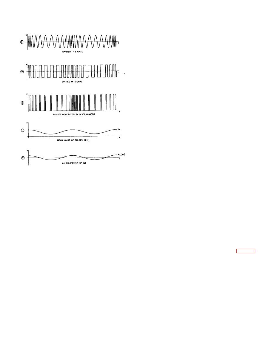
Fig. 3-2. Operation of discriminator |
|
||
| ||||||||||
|
|
 TM 11-6625-3017-14
the carrier level at the detector, while in the latter
position, when the i. f. is fixed, it is used to set the mixer
input to the correct level by adjustment of the LEVEL
attenuator and also for oscillator peaking adjustment
during initial setting up of the modulation meter.
A.M./F.M. sections
The A. M. /DEV RANGE attenuator has a total
attenuation of 40 dB. The attenuation in the 1.5 and 5
kHz positions is zero, and in the other deviation positions
increases by 10 dB per step, providing the deviation and
modulation depth ranges on f. m. and a. m. On a. m. only
the 10 and 20 dB steps are used.
5 to 500 kHz deviation ranges:
After attenuation, the signals are passed to the 2nd
1. f. amplifier which contains an output amplifier
arranged to supply approximately 0 dBm into 600 E2 to
the OUTPUT terminals. This stage effectively isolates
the meter circuits from the OUTPUT terminals and
permits de-emphasis networks to be switched in to the
output terminals when required, without affecting the
meter reading. The peak reading meter circuit consists
of an amplifier with push-pull pair to operate the meter
diode in its most linear region.
1.5 kHz deviation ranges:
Fig. 3-2. Operation of discriminator
The signal is passed to the 2nd 1. f.
amplifier which supplies approximately -10 dBm into 600
From this point onwards, all sections are common
Ω to the output terminals. Unlike the other deviation
to f. m. and a. m. and it is necessary to return to the i. f.
ranges the meter circuits are connected to the output of
amplifier and consider the a. m. sections of the
the amplifier and thus the de-emphasis networks will
modulation meter before proceeding to describe these
affect the meter reading.
final sections.
Calibration circuit
A.M. sections
In the SET CAL position of the Function switch, the
From the i. f. amplifier, a. m. signals are passed in
calibrator produces a standard crystal controlled
the appropriate position of the Function switch to the a.
deviation signal, i.e., it produces a similar signal to that
m. detector. A diode detector is employed, preceded by
from the limiter, with a peak-to-peak amplitude
an i. f. amplifier stage, the gain of which is variable by the
corresponding to a 200 kHz deviation. For a more
SET A. M. control to standardize the carrier level at the
complete description of the calibrator, refer to sect. 3. 8.
detector. When the carrier level is correct, the d. c.
output from the detector produces a reading at the SET
It thus provides a means of standardizing the
line on the meter.
discriminator and 1. f. circuitry in order that accuracy can
be maintained and also a means of checking for all
After detection, the signal is fed via a 50 kHz low-
possible sources of drift.
pass filter to the A M. /DEV RANGE switch and other
common a. m. /f. m. sections.
3.2 POWER UNIT (Unit A13--Fig. 7-6)
The d. c. component of the detected a. m. signal is
Occupying the rear corner behind the oscillator
fed direct to the meter in the SET A. M. and TUNE
compartment, the power unit includes two power
OSCILLATOR positions of the Function switch. In the
transistors fitted to heat sinks on the chassis, a printed
former position the d. c. component, which is
board and electrolytic capac-
independent of a. m., is used as already stated to set
3-2
|
|
Privacy Statement - Press Release - Copyright Information. - Contact Us |
