 |
|||
|
|
|||
|
Page Title:
LOW-PASS FILTERS (Units A6 and A8-Fig. 7-3) |
|
||
| ||||||||||
|
|
 TM 11-6625-3017-14
Since the multivibrator runs at constant frequency,
200 kHz and 15 kHz
the positive-going pulses from Q4 are at equal time
intervals. Q7 and Q8 divide these 4 kHz pulses by two
These filters are 3 dB down at 250 and 28 kHz
and produce an exactly 1:1 square wave output, via C11,
respectively to obtain optimum flatness over their pass
at about 2 kHz. Q5 and Q6 operate as a gating circuit
ands of 200 and 15 kHz. In order to accommodate the
controlled at 2 kHz by this square wave.
channel separation requirements of stereo broadcast
monitoring, the filter designs are such as to provide a
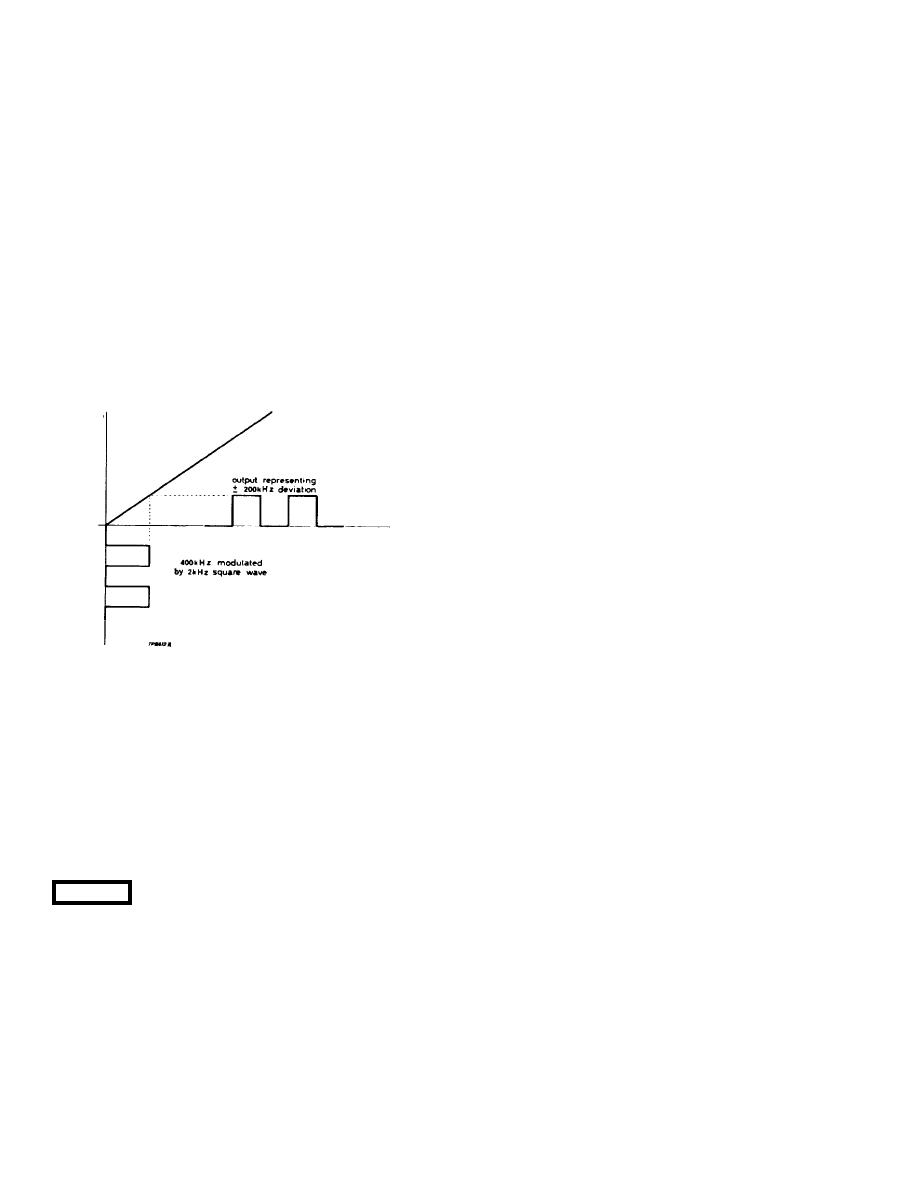
Q3 is an oscillator accurately controlled at 400 kHz
linear phase frequency response.
by crystal XLI and gated on and off by Q5 and Q6 at 2
kHz. Thus the 400 kHz signal is divided into bursts of r.f.
The 200 kHz filter integrates the pulses from the
at a repetition frequency of 2 kHz and a 1:1 on/off ratio -
discriminator and rejects the i. f. signal; thus it produces
see Fig. 3-4. This is fed to the discriminator via C9 when
a low frequency voltage which is proportional in
SB is at position SET CAL and corresponds, for
amplitude to the deviation. The 15 kHz filter restricts the
calibration purposes, to a crystal controlled deviation of
bandwidth to the audio range and can be switched in as
200 kHz. It should be noted that, in this mode, the 15
required by switch SE.
kHz filter is always in circuit to reduce the tendency of
3.10 1st L.F. AMPLIFIER (Unit A7 Fig. 7-3)
high frequency ringing due to the use of a square wave
for calibration.
Demodulated signals from the discriminator reach
the first 1. f. amplifier via the 200 kHz low-pass filter. The
amplifier has three stages, Q1 and 2 being a current
feedback pair, while Q3 and 4 are arranged as a special
low impedance configuration known as an 'emitter-
squared follower.
The amplifier has been designed to give high
stability, large bandwidth and constant gain with
immunity from h. t. changes, by virtue of its feedback
loops. C6 carries positive feedback over part df the
circuit to increase the gain, while R8 carries d. c. bias to
the first stage. C5 and R7 take a. c. negative feedback to
the first stage via the SET CAL F. M. control. The output
stage, Q3 and Q4, gives a very low impedance, so that
the output impedance of the amplifier is due almost
entirely to R14. A high stability resistor is used here to
Fig. 3-4. Derivation of standard
give optimum matching to the following switched 15 kHz
deviation signal from
filter. Similar considerations apply to the input stage,
400 kHz oscillator
where the impedance is effectively lowered by parallel
negative feedback, and R2 matches the preceding unit,
The calibrator operates only in the SET CAL
the 200 kHz low-pass filter
position of the Function switch, being switched off at all
other positions. A single attenuator pad contains the
Range attenuator (Chassis A0-Fig. 7-1)
variable resistor AORV3 (see Fig. 7-1). This resistor
(fitted immediately behind the calibrator board on the
Between the first and second 1. f. Amplifiers is the
chassis) can be used to standardize the meter deflection
range attenuator. The 1.5 and 5 kHz ranges are directly
to the SET mark.
connected, but for each succeeding range 10 dB
attenuation is switched into circuit. Two meter scales are
CAUTION
Do not attempt to SET CAL on the 1.5 kHz
used alternately to give 10 dB steps.
f. m. deviation range.
3.11 2nd L.F. AMPLIFIER (Unit A9-- Fig. 7-4)
3.9 LOW-PASS FILTERS (Units A6 and A8-Fig. 7-3)
The action of Q1 and Q2 in this unit is similar to that
of the first two transistors in the first 1. f. amplifier. RV1
in the feedback loop sets the gain. Two connections are
made after
3-5
|
|
Privacy Statement - Press Release - Copyright Information. - Contact Us |
