 |
|||
|
|
|||
|
|
|||
| ||||||||||
|
|
 (10) Replace the adapter (7).
(4) Use antiseize compound or tape on the hose
fitting threads. Connect both hose assemblies (5) to the
b. Assembly.
adapter (7).
(5) Holding the pressure regulator (14) connect the
adapter (7) to the nut (6).
(1) Place a preformed packing (8) on the threads
(6) Cross both hose assemblies (5) and connect
of the safety valve (9).
the quick-disconnect coupling (3) to the pipe and cap
(2) Connect the safety valve (9) to the adapter (7).
assembly (4).
(3) Connect the shutoff valve (2) to the adapter (7).
(7) Lace the carrier pack to the frame.
Connect the tube (1) to the shutoff valve (2).
(8) To install the pressure tank and valve assembly
refer to TM 3-1040-214-12.
Section III. AGENT SECTION
2-5. Outer Hinge
Direct support maintenance personnel are authorized to
replace the outer hinge on the agent tank.
a. Removal.
(1) Remove the pressure tank and valve assembly.
Refer to TM 3-1040-214-12.
(2) Install the dust cap (13, fig. 2-5) on the plug.
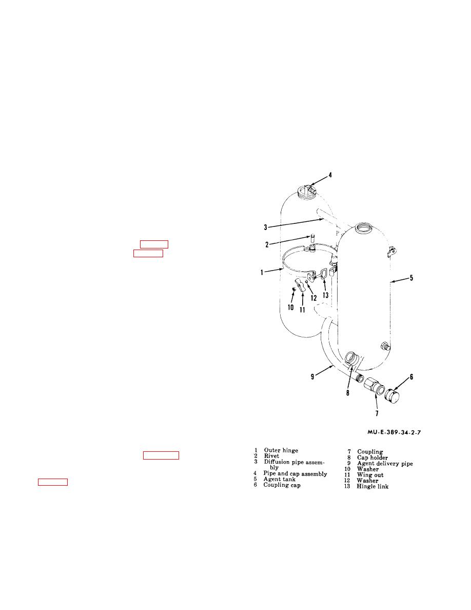
(3) Remove the rivet (2, fig. 2-7) and outer hinge
(1).
b. Assembly and Installation.
(1) Install the outer hinge (1) and rivet (2).
(2) Peen the end of the rivet to hold the outer hinge in
place.
(3) Install the pressure tank and valve assembly.
Refer to TM 3-10410-214-12.
2-6. Agent Tanks
Direct support maintenance personnel are authorized to
replace the agent tank. No welding is authorized on the
agent tanks. Unserviceable agent tanks, including the
tank connector, diffusion pipe assembly, and agent
delivery pipe, must be replaced as a unit.
a. Removal.
(1) Remove the pressure tank and valve assembly.
Refer to TM 3-1040-214-12.
(2) Remove the cords (9, fig. 2-8) and carrier
pack.
(3) Disconnect the quick-disconnect coupling half,
(3, fig. 2-6) on each hose assembly.
(4) Hold the pressure regulator (14) and
disconnect the diffusion tube nut (6) from the adapter (7).
Figure 2-7. Agent tanks
2-8
|
|
Privacy Statement - Press Release - Copyright Information. - Contact Us |