 |
|||
|
|
|||
|
Page Title:
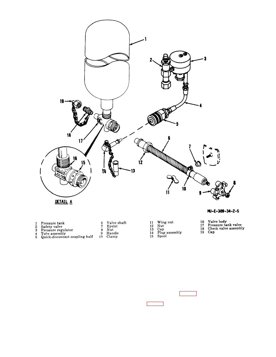
Figure 2-5. Pressure tank and valve assembly |
|
||
| ||||||||||
|
|
 Figure 2-5. Pressure tank and valve assembly
c. Assembly and Installation
2-4. Adapter
.
(1) Slide the coupling nut (12) on the valve shaft
Direct support maintenance personnel are authorized to
(6).
replace the safety valve adapter.
(2) Install the handle (9). Install and tighten the
nut (8).
a. Removal.
(3) Connect the valve shaft (6) to the pressure
tank valve (17). Connect and tighten the coupling nut
(1) Close the pressure tank valve by turning the
(12).
valve handle (B, fig. 2-1) clockwise.
(4) Install the clamp (10) and eyelet (7).
(2) Open the shutoff valve by turning the handle
Tighten the clamp and valve shaft to the stud on the
(fig. 1-1) counterclockwise.
agent tank with the wing nut (11).
(3) Remove the pressure tank and valve
assembly. Refer to TM 3-1040-214-12.
2-6
|
|
Privacy Statement - Press Release - Copyright Information. - Contact Us |