 |
|||
|
|
|||
|
|
|||
| ||||||||||
|
|
 b. Cleaning and Lubricating.
(1) Clean the removed serviceable parts if
required.
(2) Clean the valve body cavity.
(3) Before installing the trigger, apply silicon
lubricant to the trigger cavity.
c. Assembly and Installation
(1) If the trigger safety has been removed,
perform the following:
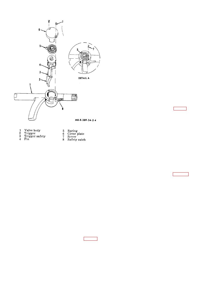
(a) Place the trigger safety (3) on the
trigger (2).
(b) Install the pin (4) to secure the trigger
safety (3) to the trigger (2).
(c) Apply silicon lubricant on the trigger.
(2) Install the trigger (2) in the valve body cavity.
(3) Position the trigger safety (3) so that it
engages the safety catch (8).
(4) Place the spring (5) on top of the trigger (2).
The center of the spring should be engaged in the slot in
the trigger shaft as shown in detail A, fig. 2-4.
WARNING
The spring must be installed under
tension.
Care must be exercised
when in- stalling the spring.
(5) Install temporarily a screw (7) as shown in
Figure 2-4. Trigger and safety assembly.
detail A.
(6) With a pair of pliers, squeeze the ex- tended
Care must be exercised when removing
end of the spring (5) and temporarily in- stall screw (7)
the spring.
until the extended end of the spring is seated properly in
(3) Remove the spring (5) and trigger (2) from
the valve body cavity.
the valve body cavity.
(7) Remove screw (7, detail A).
(4) If the trigger safety must be replaced perform
(8) Install the cover plate (6) and two screws (7).
the following:
(9) Install the removed parts (para 2-1b).
(a) Remove the pin (4).
(b) Remove the trigger safety (3) from
the trigger (2).
Section II. PRESSURE SECTION
(2) Disconnect the coupling nut (12) from the
2-3. Valve Shaft Assembly
pressure tank valve (17).
(3) Remove the wing nut (11), eyelet (7), and
Direct support maintenance personnel are authorized to
clamp (10).
replace the valve handle, clamp, eye- let, and coupling
(4) Remove the nut (8) and handle (9).
nut.
b. Inspection.
a. Removal.
(1) Inspect the removed parts, including the
(1) Close the pressure tank valve (17, fig. 2-5) by
coupling nut (12) and valve shaft (6), for possible
turning the handle (9) clockwise.
damage. Check especially the threads on the nut.
(2) Replace unserviceable parts.
2-5
|
|
Privacy Statement - Press Release - Copyright Information. - Contact Us |