 |
|||
|
|
|||
|
Page Title:
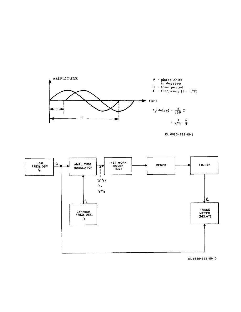
Figure 5-2. Basic delay measuring system. |
|
||
| ||||||||||
|
|
 TM 11-6625-922-15
with signal No. 4 to provide an output signal in the 0.1
heterodyne method for providing the output signal. A
variable frequency signal (1) is generated in the variable
kHz to 50 kHz range (7). Signal range (6) or (7) is then
selected by switch S3 and output amplifier A12 amplifies
frequency oscillator assembly (A2) which is buffered in
A16 to provide 2-2.6 MHz and 200 kHz-260 kHz range
the modulated signal and sends it to the TRANSMIT
output.
signals (3 and 4). The 2 MHz oscillator (A4) provides a
stable 2 MHz signal (2) which is divided by 10 in A10 to
b.
Modulation Frequency Generation.
The
provide a 200 kHz signal (5). Signal No. 2 is modulated
in A14 and then heterodyned with signal No. 3 to give
modulating frequencies of 25 Hz, 83 1/3 Hz, and 250 Hz
an output signal in the 50 kHz to 552 kHz range (6).
are generated by digital logic division from
Signal No. 5 is modulated in A15 and then heterodyned
Figure 5-1. Time Delay.
Figure 5-2. Basic delay measuring system.
5-2
|
|
Privacy Statement - Press Release - Copyright Information. - Contact Us |