 |
|||
|
|
|||
|
Page Title:
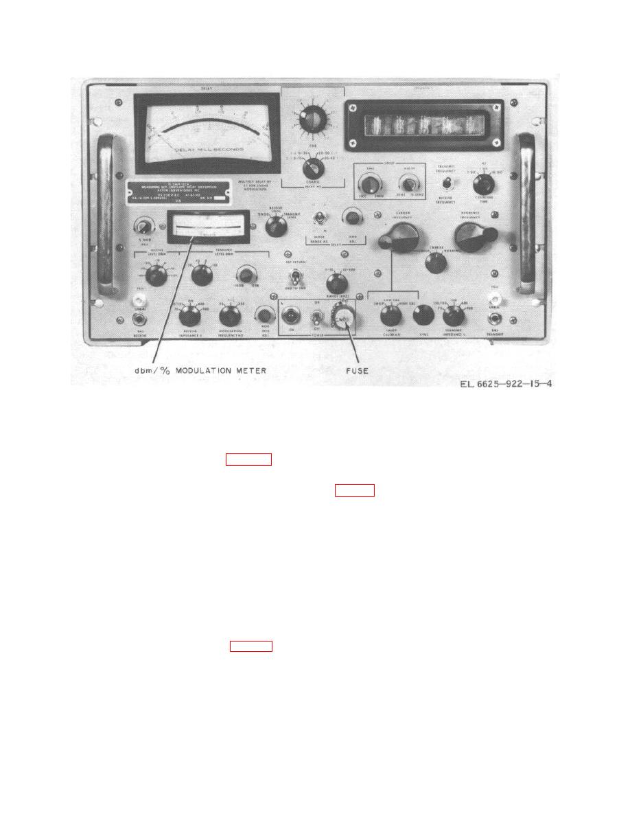
Figure 3-1. Operator's controls and indicators. |
|
||
| ||||||||||
|
|
 TM 11-6625-922-15
Figure 3-1. Operator's controls and indicators.
b. End-to-End with Return Reference. When two
3-3. General Operating Procedures
transmission lines are available, one of the lines can be
used to return the time-delay information of the line
a. The TS-2669/GCM must be connected to a 115-
under test back to the transmitting point (fig. 3-4). The
or 230- volt ac power source by the power cable at the
modulated carrier produced by the transmitting TS-
rear of the unit. Before doing this, check to make sure
2669/GCM is sent down the test line. At the end, the
the unit is internally strapped for the proper line voltage
signal is demodulated by a receiving TS-2669/GCM and
the modulation component is remodulated onto a fixed
frequency reference carrier signal produced by the
Caution: The TS-2669/GCM must be
receiving TS-2669/GCM. This reference signal is sent
grounded by the ground terminal on
back to the receiver section of the transmitting TS-
the UP-121/M connector on the
2669/GCM. The signal received at the transmitting TS-
power cable or a shock hazard may
2669/GCM contains phase shifts corresponding to the
result.
delay of the measured line plus the fixed delay
introduced by the auxiliary channel; therefore, relative
b. Operate the POWER switch to ON. Check to
delay measurements can be made on the measured line
see that the POWER ON indicator is lighted. Allow a 1-
section.
With this system, the required delay
minute warmup period.
measurements can be made from the transmitting
c. Operate the REF RETURN-END TO END switch
TS2669/GCM. However, the amplitude characteristic of
to END TO END.
the line under measurement must be made at the
d.
Operate the % MOD-RECEIVE LEVEL-
receiving TS-2669/GCM.
TRANSMIT LEVEL switch to % MOD. Operate the
c. Loop Mode. In the loop method (fig. 3-5), the
MODULATION FREQUENCY HZ switch to the desired
line to be tested is connected at the far end to a second
modulating frequency (25, 83-1/3, or 250 Hz). Note that
line returning the signal to the TS-2669/GCM.
the modulating frequency to be used must be one-
Transmission and reception are conducted at the same
quarter of the lowest carrier frequency to be used or
location, and delay and amplitude measurements can
less, for example:
be made easily. In the loop mode, delay of the forward
and return paths cannot be separated; therefore, it is
Mod freq
Lowest carrier freq to be used
assumed that the forward and return path characteristics
25 Hz
100 Hz
are equal.
83 1/3 Hz
334 Hz
250 Hz
1,000 Hz
3-4
|
|
Privacy Statement - Press Release - Copyright Information. - Contact Us |