 |
|||
|
|
|||
|
Page Title:
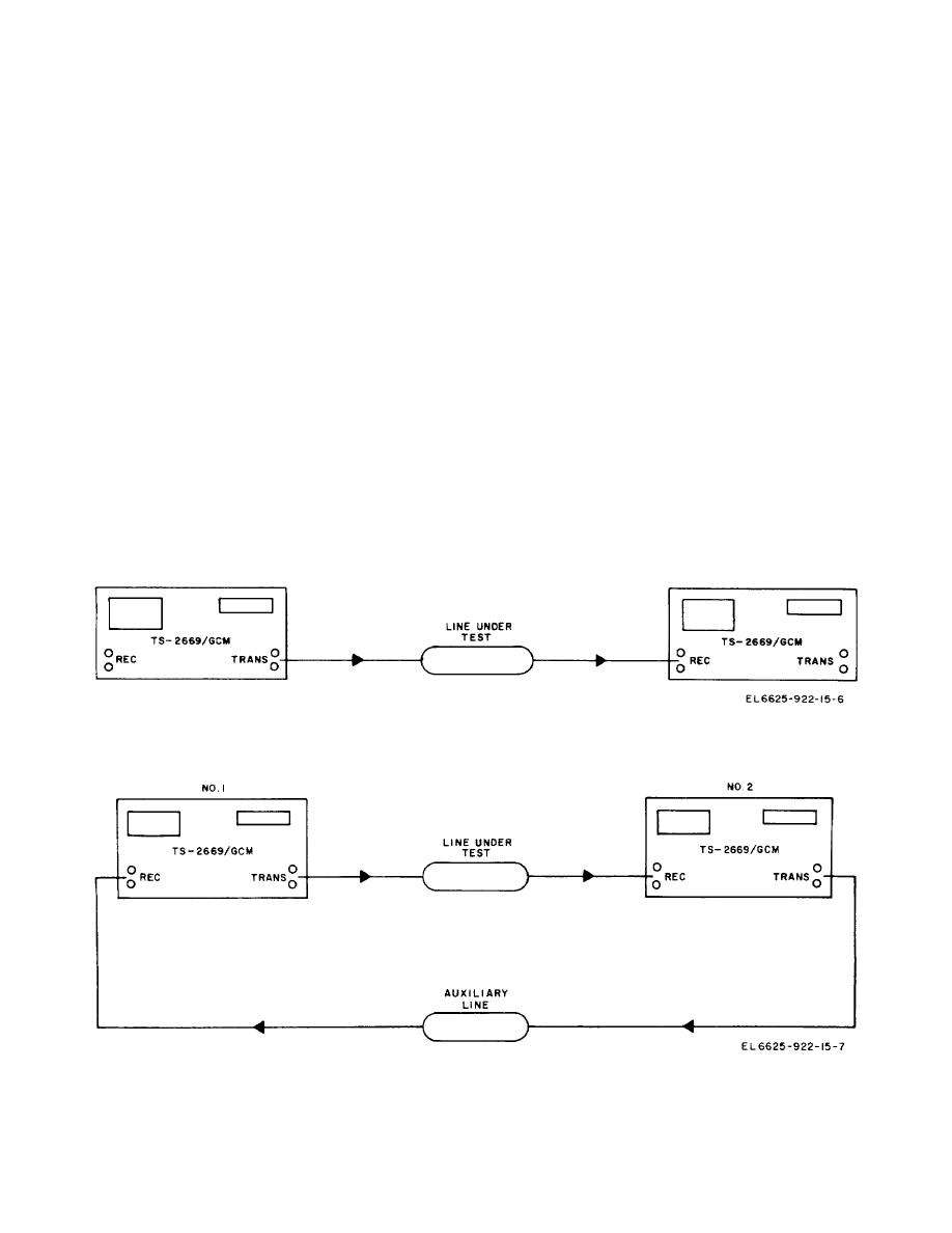
Figure 3-4. Connections for end-to-end with return reference |
|
||
| ||||||||||
|
|
 TM 11-6625-922-15
output signal only at the 75 Ω UNBAL TRANSMIT jack
(1) For operation in the voice-frequency band
(300 Hz to 3,400 Hz), use the 25-Hz modulating
and is usable only in the 50- to 552-kHz frequency
frequency.
range. The 130/135-, 150-, 600-, and 900-ohm positions
(2) Operate the % MOD ADJ control to obtain a
provide an output only at the BAL TRANSMIT jack and
reading of 45 to 50 percent on the dbm/%
are usable only in the 0.1 to 110-kHz frequency range.
MODULATION meter.
Whenever the modulating
frequency is changed, always adjust the % MOD ADJ
Caution: Do not connect the UNBAL
control to maintain the 45- to 50 percent modulation
TRANSMIT or B3AL TRANSMIT jacks
level.
directly to a line having a dc
e. Operate the MOD FREQ ADJ control fully
potential.
Use external coupling
counterclockwise (ccw) and then 5 turns clockwise (cw)
capacitors for isolation.
f. Operate the TRANSMIT FREQUENCY-RECEIVE
FREQUENCY switch to TRANSMIT FREQUENCY.
l. The output signal at either TRANSMIT jack
g. Operate the SWEEP-CARRIER-REFERENCE
cannot be monitored for amplitude by the dbm/%
switch to CARRIER.
MODULATION meter, which reads actual power in dbm
h. Operate the TRANSMIT LEVEL DBM control
into the transmission line load, relative to one milliwatt.
fully cw.
The impedance switching arrangement automatically
i. Operate the COUNTING TIME switch to 1 SEC.
corrects the signal line voltage so that only power is
j.
Operate the % MOD-RECEIVE LEVEL-
read on the dbm/% MODULATION meter.
The
TRANSMIT LEVEL switch to TRANSMIT LEVEL.
frequency of the transmit signal may be monitored by
the FREQUENCY display in Hz. The transmit signal
to the position required to match the impedance (75
level is read by adding the db reading on the
ohm, 130/135, 150, 600, or 900) of the transmission line
TRANSMIT LEVEL DBM switch to the indication on the
to be measured. The 75-ohm position provides an
Figure 3-3. Connections for end-to-end mode.
Figure 3-4. Connections for end-to-end with return reference.
3-6
|
|
Privacy Statement - Press Release - Copyright Information. - Contact Us |