 |
|||
|
|
|||
|
Page Title:
S e c t i o n 1. BLOCK DIAGRAM ANALYSIS |
|
||
| ||||||||||
|
|
 TM 11-6625 -537-14-1
CHAPTER
5
FUNCTIONING
OF
EQUIPMENT
S e c t i o n 1. BLOCK DIAGRAM ANALYSIS
5-1. General
power supply and a voltage divider. The 500-volt
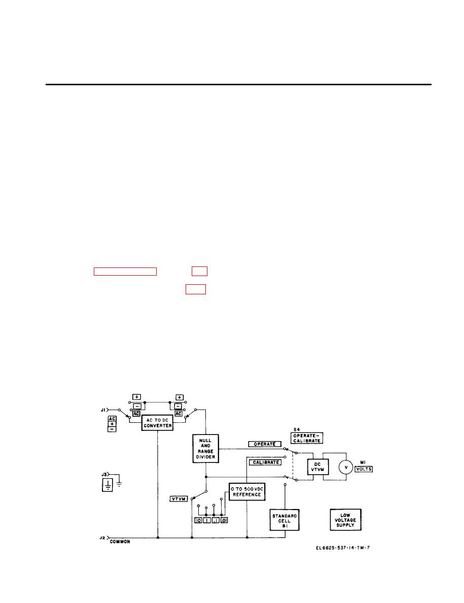
(fig. 5-1)
power supply is a conventional series-regulated
supply with a single regulation stage. The output
Electronic Voltmeter ME-202 (*)/U is a precision
of the supply is set to 500 volts by using the dc
voltmeter used to accurately measure ac or dc
vtvm to compare a precise sample of the output
potential between O and 500 volts, It basically
voltage with the voltage of standard cell B 1. The
consists of a dc vacuum tube voltmeter (vtvm, a
500-volt power supply also provides B + to the
O- to 500-volt dc reference, a null and range
ac-to-dc converter.
divider, an ac-to-dc converter, and a low voltage
c. Null and Range Divider. The null and range
supply. T h e s e units are shown in the block
divider selects the magnitude of input voltage to
diagram and are discussed in a through e below.
the de vtvm. The output of the divider is con-
The electronic voltmeter functions as a con-
trolled by the RANGE and NULL switches.
ventional vtvm when the NULL switch is set to
d. Ac-to-Dc Converter.The ac to dc converter
VTVM, and as a differential voltmeter when the
converts all ac input voltages to a dc voltage
NULL switch is set to 10, 1, .1, or .01. The
which is proportional to 1.11 times the average
functioning o f the electronic v o l t m e t e r is
value of the input waveform. If the input ac is of a
presented in paragraphs 5-2 through 5-6. The
single frequency, the dc output of the converter
explanation is supported by block diagrams and
will be proportional to the root-mean-square (rms)
partial schematic diagrams. See figure FO-6 for a
value of the input. The converter provides a dc
complete schematic diagram of the electronic
output of 5 volts when full range voltage is ap-
voltmeter.
plied to the electronic voltmeter in each range.
a. Dc Vtum. The dc vtvm indicates the dif-
The output of the converter is applied to the dc
ference between the input voltage and the O- to
vtvm in the vtvm mode of operation, or compared
500-volt dc reference in the electronic voltmeter
to O- to 500-volt dc reference in the differential
mode. In the vtvm mode, the dc vtvm indicates
voltmeter mode.
the value of the unknown voltage directly on the
e. Low Voltage Supply. The low voltage supply
VOLTS meter.
provides B + to the dc vtvm and filament voltage
b. O- to 500-volt Dc Reference. The O- to 500-
as required.
volt dc reference is obtained from a 500-volt dc
5-1
Figure
5-1.
Electronic
ME-202(*)/'U,
block
diagram.
|
|
Privacy Statement - Press Release - Copyright Information. - Contact Us |