 |
|||
|
|
|||
|
Page Title:
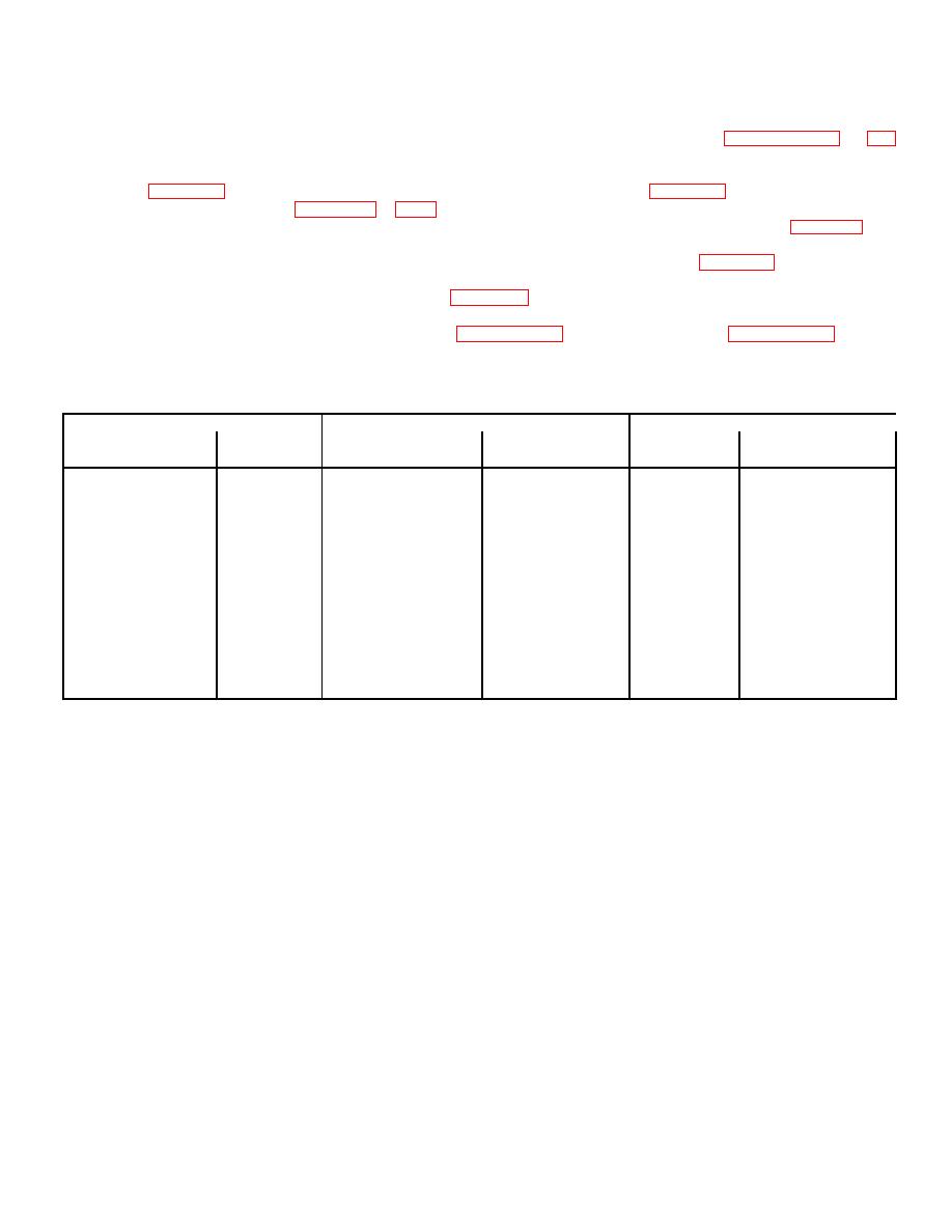
Table 5-3. Backplane Harness Assembly Wiring Chart |
|
||
| ||||||||||
|
|
 TM 11-5895-1179-13 E132-EA-OMP-010/E106 KY883 TO 31S1-2GGSC-161
5-29.
Removal, Replacement and Repair of Backplane Harness Assembly A8A5
a.
Remove the chassis cover and four plug-in-circuit card assemblies as described in paragraphs 5-6 and 4-7,
respectively.
b.
Make certain capacitors A7C1 and A5AIC1 are discharged. Remove the terminal board cover from A7TB1
(figure 5-5) and tag and remove the wires from A7TB1-2, -4, -5, and -7 (figure 5-2). Tag and remove all the
wires from ASAlTBl (figures 5-5 and 5-6) and remove the backplane harness assembly. If an individual wire
is to be replaced, cut the tiedown straps as necessary and remove the desired wire using table 5-3 as a
guide.
c.
When repairing the backplane harness assembly, construct a new wire per table 5-3. A MS90413-lA
crimping tool will be required.
d.
Install the new backplane harness assembly (figure 5-2).
e.
Install the terminal board cover on A7TB1.
f.
Install the four plug-in-circuit card assemblies (paragraph 4-7) and the chassis cover (paragraph 5-6).
g.
Close and secure the front panel assembly.
Table 5-3. Backplane Harness Assembly Wiring Chart
From
To
Wire
Type
Type
Length
AWG Size
Location
Connection
Location
Connection
(Inches)
and Color
A5AITBl-GND
Terminal
A7TB1-7
Terminal Lug
7.00
14,green
Solderless
MS02536-106
4916
A5AlTB1-AC1
Terminal
A7TB1-2
Terminal Lug
8.50
14,white/
Solderless
MS02536-106
orange
4916
ASAITBl-AC2
Terminal
A7TB1-4
Terminal Lug
7.75
14,yellow
Solderless
MS02536-106
4916
A5AITBl-FILTER
Terminal
A7TB1-5
Terminal Lug
6.75
14,orange
Solderless
MS02536-106
4916
5-26
|
|
Privacy Statement - Press Release - Copyright Information. - Contact Us |