 |
|||
|
|
|||
|
Page Title:
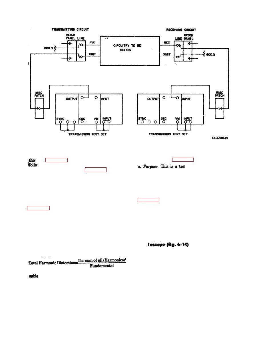
Figure 6-11. Terminal impedance test for receive circuit. |
|
||
| ||||||||||
|
|
 TM 11-5895-1012-10
act as transmitter, prepare the transmitting circuit
Level Test (fig. 6-13)
wn in figure 6-12 and set transmission test set as
ws:
t of operating conditions
(a) Jumpered as shown in figure 6-12.
rather than a measurement of circuit parameters. As
(b) Patch panel impedance selectors at 600
such, this test is not applicable as an in-station or
ohms.
maintenance test.
(c) Patch panel frequency selector at less than 5
b. Test Equipment. A noise measuring test set and
KHz.
patch cords are required to perform this test.
(d) Turn on voltmeter.
c. Procedure. Prepare the test arrangement shown
(2) Receiving Circuit. If the local station is to act
in figure 6-13 and set the noise measuring test set for
as receiver, prepare the receiving circuit shown in
selector for high pass filtering. The circuit being tested
as follows:
should be in service and the connection should be made
(a) Input impedance control at 600 ohms.
at the VF patch panel. Read and record the indications
(b) Bandwidth to 200 or 250 Hz.
on the noise measuring test set.
(3) Procedure. Transmitting station will calibrate
d. Performance Standard. The required composite
the transmission test set for a 700 Hz, - 10 dbm0 out-
level is the reference level minus 13 dbm0.
put. Receiving station will measure the circuit level of
the fundamental (700 Hz), second harmonic (1400 Hz),
Hz). Calculate the total harmonic distortion using the
a. Purpose. This test will measure phase jitter of a
following expression:
circuit between stations or within a station and deter-
mine circuit compliance with minimum operating
requirements. Phase jitter is the instantaneous de-
viation from the average phase of the signal and may
(4) Performance Standard. The maximum permis-
be caused by channel induced phase noise or by
total harmonic distortion is -40 dbm0.
additive amplitude noise. Phase jitter may be
d. In-Station Test. I n - s t a t i o n t e s t i n g i s a c -
measured using an oscilloscope or using a phase jitter
complished in the same manner as station to station
meter. The procedure for measuring phase jitter using
testing except the local station acts as both trans-
an oscilloscope is given below. The procedure for
mitter and receiver.
|
|
Privacy Statement - Press Release - Copyright Information. - Contact Us |
