 |
|||
|
|
|||
|
Page Title:
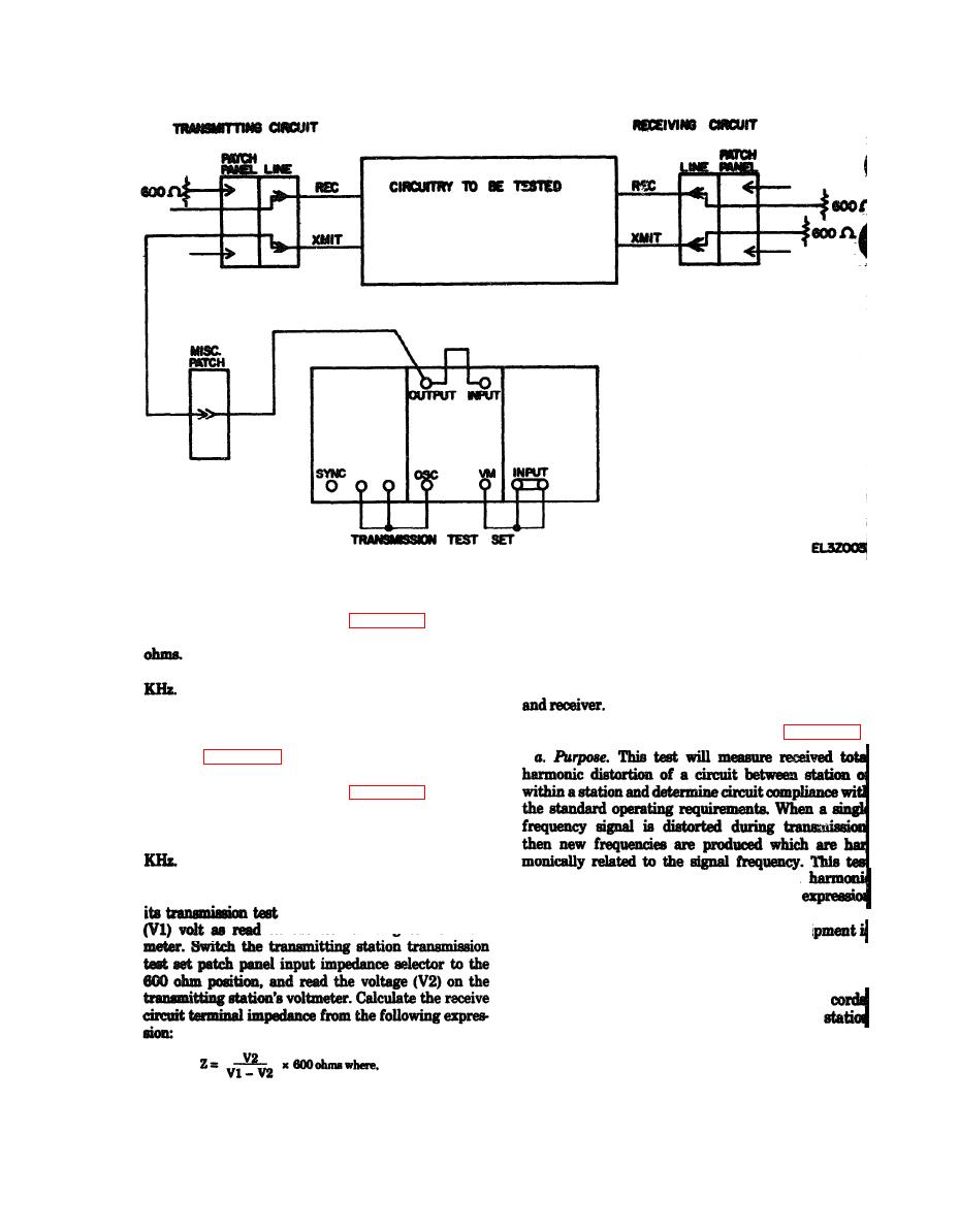
Figure 6-10. Terminal impedance test for transmit circuit. |
|
||
| ||||||||||
|
|
 TM 11-5895-1012-10
V2=
receiving station voltage terminated in 600 ohms
ure 6-11 and set the transmission test set as follows:
(4) Performance Standard. The permissable ter-
(a) Jumpered as shown in figure 6-11.
minal impedance is 600 ohms 10%.
(b) Patch panel impedance selectors at 600
d. In-Station Test. In-station testing is accom-
plished in the same manner as station to station test-
(c) Patch panel frequency selector at less than 5
ing except the local station acts as both transmitter
(d) Voltmeter function switch to on.
(2) Transmitting Circuit. If the local station is to
act as transmitter, prepare the transmitting circuit
shown in figure 6-11 and set the transmission test set
as follows:
(a) Jumpered as shown in figure 6-11.
(b) Patch panel input impedance selector at
(c) Patch panel frequency selector at less than 5
(d) Voltmeter function switch to on.
measures the signal frequency and each
(3) Procedure. The receiving station will calibrate
separately and then gives a mathematical
set for 1000 Hz and set it for 1
for computing the total harmonic distortion.
o n the transmitting station volt-
b. Test Equipment. The following test equi
required to perform this test:
(1) Transmission Test Set.
(2) Frequency Selective Voltmeter.
(3) Terminating plugs (600 ohms) and patch
c. Station-to-Station Test. Contact distant
and arrange for one station to act as transmitter and
one as receiver. Perform the procedure below and the
reverse roles and repeat the procedure.
V1=
receiving station open circuit voltage
(1) Transmitting Circuit. If the local station is to
|
|
Privacy Statement - Press Release - Copyright Information. - Contact Us |