 |
|||
|
|
|||
|
Page Title:
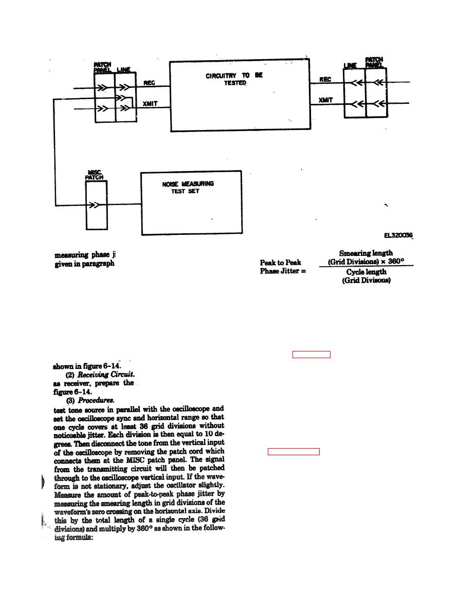
Figure 6-13. Composite signal transmission level test. |
|
||
| ||||||||||
|
|
 TM 11-5895-1012-10
itter using a phase jitter meter is
6-16.
b. Test Equipment. The following test equipment is
required to perform this test:
(1) Test Tone Source, 1000 Hz at - 10 dbm (2 re-
(4) Performance S t a n d a r d . T h e m a x i m u m
permissable peak-to-peak phase jitter is 15 degrees.
quired).
d. In-Station Test. I n - s t a t i o n t a s t i n g i s a c -
(2) Oscilloscope.
C. Station-to-Station Test. Contact distant station
complished in the same manner as station to station
and arrange for one station to act as transmitter and
testing except the local station acts as both trans-
one as receiver. Perform the procedure below and then
mitter and receiver.
reverse roles and repeat the procedure.
(1) Transmitting Circuit. If the local station is to
Meter (fig. 6-15)
act as transmitter, prepare the transmitting circuit
a Purpose. This test will measure phase jitter of a
circuit between stations or within a station and deter-
If the local station is to act
mine circuit compliance with minimum operating
receiving circuit shown in
requirements. Phase jitter is the instantaneous de-
viation from the average phase of the signal and may
. At the receiving station, patch the
be caused by channel induced phase noise or by ad-
ditive amplitude noise. Phase jitter may be measured
by using a phase jitter meter or an oscilloscope.
The procedure for use with a phase jitter meter is
given below. The procedure for using an oscilloscope is
given in paragraph 6-15.
b. Teat Equipment. The following test equipment is
required to perform this test:
(1) T&Tone Source, 1000 Hz at - 10 dbm.
(2) Phase Jitter Meter.
c. Station-to-Station Test. Contact distant station
and arrange for one station to act as transmitter and
one as receiver. Perform the procedure below and then
reverse roles and repeat the procedure,
(1) Transmitting Circuit. If the local station is to
act as transmitter, prepare the transmitting circuit
|
|
Privacy Statement - Press Release - Copyright Information. - Contact Us |
