 |
|||
|
|
|||
|
Page Title:
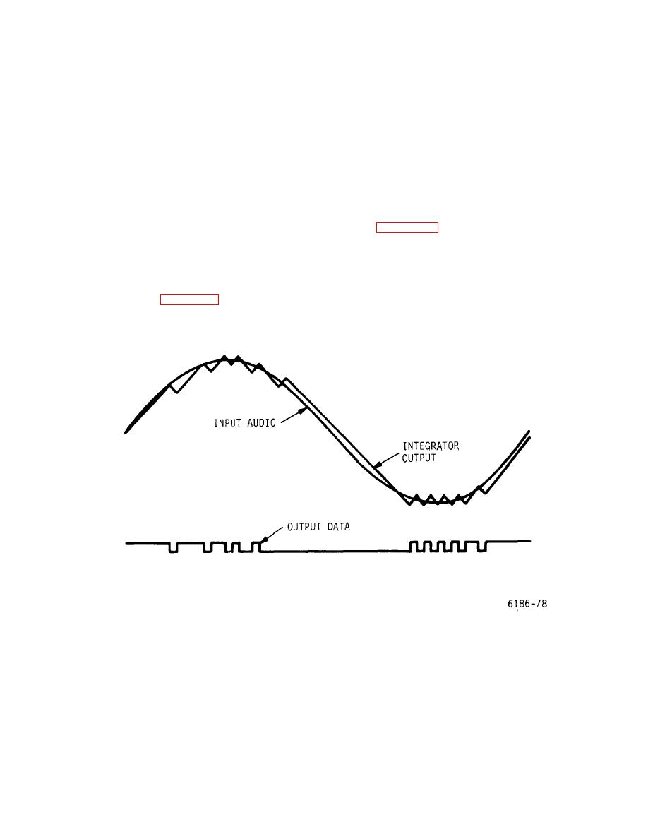
Figure 5-21. VE Card - Waveform Diagram |
|
||
| ||||||||||
|
|
 T.O. 31W2-2GSC24-2
TM 11-5805-688-14-1
NAVELEX 0967-LP-545-3010
voltage to the positive inhibit switch. The polarity of the
to maintain a decreasing error voltage condition. Once
bit 1 (one or zero) signal applied to the two switches
the error voltage equals or exceeds the filtered audio
determines which switch is enabled to apply either the
signal voltage, the error signal polarity out of the
negative drive or the positive drive signal to the
comparator switches from a one to a zero, or from a zero
integrator. The integrator, in turn, responds to the
to a one, thus interrupting the successive string of the
applied drive voltage and produces the reconstructed
same polarity pulses from the comparator. The boost
analog signal that is applied through a buffer to the
enable output from the logic decoder output then returns
comparator.
to its normal decreased drive state until the next series of
three ones or zeros is generated from the comparator to
5-255. When the decoder logic generates the boost
indicate the need for a faster correction voltage change.
enable signal, the active negative or positive drive signal
applied to the integrator increases in amplitude to
5-256. Figure 5-21 illustrates the relationship between
produce a sharper slope for the drive signal applied to
the data output pulses (MDTOXX-) and the
the integrator. The integrator output, in turn, has a
reconstructed analog signals from the integrator. The
sharper rising or falling slope that enables the
figure also shows how the reconstructed analog signal
reconstructed analog signal voltage to increase at a
effectively tracks the filtered audio signal.
When
greater rate, thus decreasing the error output from the
decoded in a demultiplexer, the reconstructed analog
comparator. As shown in figure 5-21, the reconstructed
signal will be a true reproduction of the original filtered
analog voltage waveform requires continuous corrections
audio
signal.
Figure 5-21. VE Card - Waveform Diagram
5-64
|
|
Privacy Statement - Press Release - Copyright Information. - Contact Us |
