 |
|||
|
|
|||
|
|
|||
| ||||||||||
|
|
 T.O. 31W2-2GSC24-2
TM 11-5805-688-14-1
NAVELEX 0967-LP-545-3011
CHAPTER 4
OPERATION
4-1
INTRODUCTION.
4-5. OPERATING INSTRUCTIONS.
4-2. When the multiplexer set is configured as
4-6. Paragraphs 4-7 through 4-10 contain the operating
prescribed in section I of chapter 3, the functional
procedures for the multiplexer set; no unusual or special
operation of the multiplexer is fully automatic. The
operating procedures are required. The lamp test and
operator requirements for operating the equipment are
self-test procedures in paragraphs 4-8 and 4-9 can be
limited to the application of operating power. Once the
performed on an operational multiplexer set without
equipment is in operation, operator duties consist of
disrupting the functional operation of the equipment.
visual checks of the automatic diagnostic error displays
4-7. STARTING PROCEDURES.
and the performance of periodic maintenance tests.
1. Ensure that POWER CONTROL circuit breaker
4-3. CONTROLS AND INDICATORS.
is pressed to its on position.
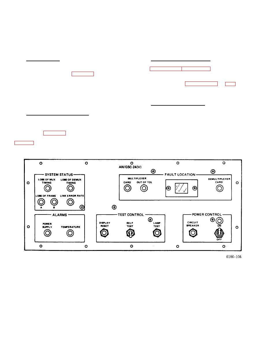
4-4. All controls and indicators are mounted on the front
2. Set POWER CONTROL switch to ON. Observe
panel of the multiplexer set. The controls and indicators
that POWER CONTROL ON indicator is lighted. Other
are shown in figure 4-1. The controls and indicators,
indicators may also be lighted.
together with their functional descriptions, are listed in
Figure 4-1. Front Panel Controls and Indicators
4-1
|
|
Privacy Statement - Press Release - Copyright Information. - Contact Us |