 |
|||
|
|
|||
|
Page Title:
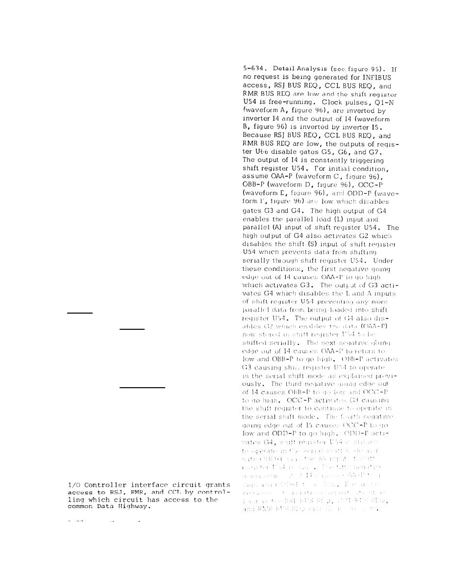
I/0 CONTROLLER INTERFACE CIRCUIT |
|
||
| ||||||||||
|
|
 T.O. 31S5-4-308-l
TM 11-5805-663-14-13
NAVELEX 0967-464-0010
and DB15-P enables FF13 to be set when
R M R C M N D CLK-P is generated. If DB11 P
and DB12-P art- both low, FF13 is cleared,
i f n e c e s s a r y , when RMR CMND CLK-P is
g e n e r a t e d . If DB11-P is high and DB12-P
is low, FF13 toggles when RMR CMND
C L K - P i s g e n e r a t e d . If DB11l-P is low and
DB12-P is high, FF13 does not change
state when RMR CMND CLK-P is generated.
If DB11-P and DB12-P are high, FF13 is
set by RMR CMND CLK-P. If any one or
rnore, but not all, data bits DB08-P through
DB10-P are low, the output of G13 is low
which disables gate G16. The low output
of G13 is inverted by inverter I22 which
enables gates G14 and G15. If DB13-P
is high at this time, G 14 is activated
which enables TF14 to be set by RMR CMND
CLK-P. If DB13-P is low, it is invertcd by
inverter I24 which activates G15. The out-
put of G15 enables FF14 to be cleared, if
n e c e s s a r y , by PMR CMND CLK-I'. If data
bits DBO8-P through DB10-I' are low the
output of G13 is high which enables gate
G 1 6 . If DB13-P is high at this time G16
i s a c t i v a t e d . The output of G17 activates
G18 which rcsets FF10 through FF14.
The outputs of FF10 through FF13 and FF14
are inverted by inverters I17 through I20
and I23, respectively. The output of I17,
D O N O R , c o m m a n d s the RMR function to
o p e r a t e i n t h e n e w d a t a r e a d m o d e . The
output of I18, DORDR, commands the RMR
f u n c t i o n t o o p e r a t e i n t h e r- v i s- d a-t a r e a d
e
e
mode. The output of I19, DOMDW, com-
mands the RMR function to operate in the
w r i t c m o d e . The output of 120, DOSED,
notifies the RMR function that A timing
The
error or detected error has occurred.
output of I23, RMR INT INH, prevents the
RMR function from requesting INFIBUS ac-
cess.
I/0 CONTROLLER
INTERFACE
CIRCUIT.
5 - 6 3 3 . G e n e r a l . The I/O Controller inter-
face circuit detects when the RSJ, CCL, or
RMR functions a r e r e q u e s t i n g I N F I B U S a c -
cess and n o t i f y t h e R S J , C C L o r R M R f u n c -
tions when they can gain INFIBUS access.
|
|
Privacy Statement - Press Release - Copyright Information. - Contact Us |
