 |
|||
|
|
|||
|
Page Title:
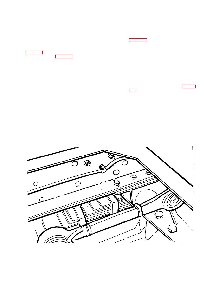
Figure 31. Crack in Lower Flange of Main Side Rail and Reinforcement Member |
|
||
| ||||||||||
|
|
 TB 9-2300-247-40
l.
Drill a 3/8-inch diameter hole at the terminal of
o. Temporarily position spacer between side rail
the crack in the reinforcement member to reduce
and reinforcing member and weld reinforcement
the tendency of the crack to continue.
angle, stiffener, and filler plate as shown in
m. Fabricate reinforcement members and angles
using cold rolled steel plate as shown in
p. Remove temporary spacer and secure
reinforcement member to side rail with new No.
place as shown in Figure 29. Check carefully for
8 bolts, washers, and locknuts.
accurate fit.
NOTE
NOTE
Do not reinstall the bottom front bolt
The angle reinforcement is added
securing the bogie bracket to the rail
after the reinforcement member is in
flange at the side. The front bolt that
place. The addition of the angle is to
must be removed from all 5-ton
provide additional metal to offset the
series vehicles is identified in Figure
loss of critical metal caused by the
crack. To avoid overheating of the
hole is to remain unused as a bolt
side
rail
during
the
welding
hole.
operation, a temporary spacer must
q. Replace
all
crossmembers,
brackets,
be
provided
between
the
components/assemblies, items, anchor bolts,
reinforcement member to be welded
and other materials removed for access to the
and the side rail.
repair work, using new bolts, washers and
locknuts for all vehicle framing members.
n. Locate and drill undersized mounting holes as
shown on the sketches and ream to the exact
r.
Thoroughly clean repaired
surfaces
and
size of the new bolts to be selected.
surrounding area of repair.
Figure 31. Crack in Lower Flange of Main Side Rail and Reinforcement Member
29
|
|
Privacy Statement - Press Release - Copyright Information. - Contact Us |
