 |
|||
|
|
|||
|
Page Title:
Defect. Main Side Rail Lower Flange And Reinforcing Member Failure |
|
||
| ||||||||||
|
|
 TB 9-2300-247-40
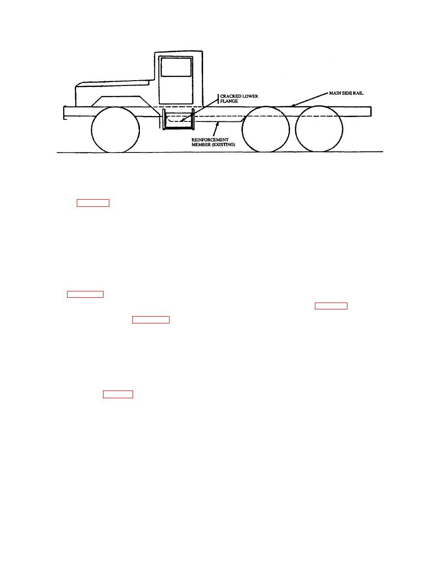
Figure 29. Crack in Lower Flange of Main Side Rail Reinforcement Member
g.
Fabricate a 3/8 x 3 x 3-inch steel angle
vehicle framing members, causing
shaped to provide an accurate fit to suit the
the metal adjacent to the weld to be
reinforcing member under repair as shown
weakened.
As a result of the
in figure 31 h. Clamp the steel angle into
destructive properties of welding on
position and bolt as indicated.
heat-treated steel, welding of heat-
treated 5-ton truck framing members
i.
Thoroughly clean repaired surfaces and
is prohibited except as otherwise
surrounding area of repair.
specified. This repair can best be
accomplished by plates secured with
j.
Prime and paint repair area and
bolts, locknuts, and washers.
surrounding surfaces as specified in TM-
43-0139.
c.
Remove the rear axle suspension
bracket, rubber bumper bracket,
k.
Verify frame alignment as specified in
and remove the crossmembers,
removing all rivets and bolts as
specified in Section I.
48.
Defect. Main Side Rail Lower Flange And
d.
Slightly deflect the side rail on the side of
failure in the lower flange of the main side rail and
the cracked crossmember.
reinforcing member approximately 12 or 13 inches
forward of the centerline of the rear axle assembly.
e.
Detach the cracked reinforcement member
from the cracked side only.
a. Thoroughly clean vehicle frame of all oil,
grease, dirt, and debris.
f.
Carefully jack up the rear of the vehicle
frame at four locations to evenly distribute
b. Perform general vehicle frame inspection as
the load and to reduce the stress at the
specified in Section I.
point of the frame defect.
NOTE
g.
Perform the necessary removal of
Heat-treated steel frames, such as
components, service lines, electrical wiring,
those used in 5-ton trucks are
etc., as required to gain access to the
assembled using bolts and rivets.
proposed repair.
Most welding processes destroy the
heat treatment properties of the
27
|
|
Privacy Statement - Press Release - Copyright Information. - Contact Us |