 |
|||
|
|
|||
|
Page Title:
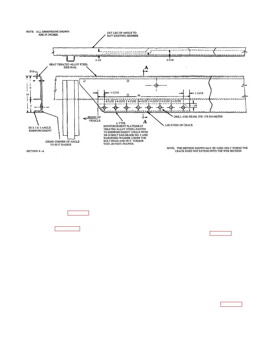
Figure 30. Reinforcement Angle for 5-Ton Truck Frame |
|
||
| ||||||||||
|
|
 TB 9-2300-247-40
Figure 30. Reinforcement Angle for 5-Ton Truck Frame
NOTE
WARNING
The rear axle suspension bracket
Use only effective chip guarding
located below the lower flange of the
equipment, protective equipment and
main side member prevents the
protective clothing (goggles, shields,
adding of reinforcement plates in this
gloves aprons, etc.) when doing any
area. However, reinforcements may
drilling, grinding, or welding. Failure
be located in the area within the
to follow this warning could result in
channel (refer to Figure 29 ).
injury to personnel.
(1) Remove bolts and rivets securing
Fabricate the reinforcing member as
brackets or other items to the frame
shown in Figure 31. The metal is
as described in Chapter 1.
being added primarily to the lower
flange. This is the principal area
(2) For tractors, remove fifth wheel anchor
where the additional support is
bolts, as required.
needed. Because metal cannot be
welded to the main side rail, the full
(3) For cargo trucks, remove cargo body
design load cannot be supported.
brackets, anchor bolts, and raise body
The metal to provide design load
for clearance.
support must be added to the
reinforcing member by welding,
j.
Using jack, deflect side rail member
using low carbon steel.
outward a distance of not more than
1/2-inch at the rear crossmember.
h.
Remove rear axle suspension bracket,
bumper bracket, on the cracked side of the
k.
Remove
defective
reinforcement
frame only.
member as shown in Figure 28.
i.
Remove
the
following
components/
assemblies as required for accessibility:
28
|
|
Privacy Statement - Press Release - Copyright Information. - Contact Us |