 |
|||
|
|
|||
|
|
|||
| ||||||||||
|
|
 TM 11-6625-937-12
CHAPTER 2
INSTALLATION
2-1. Unpacking
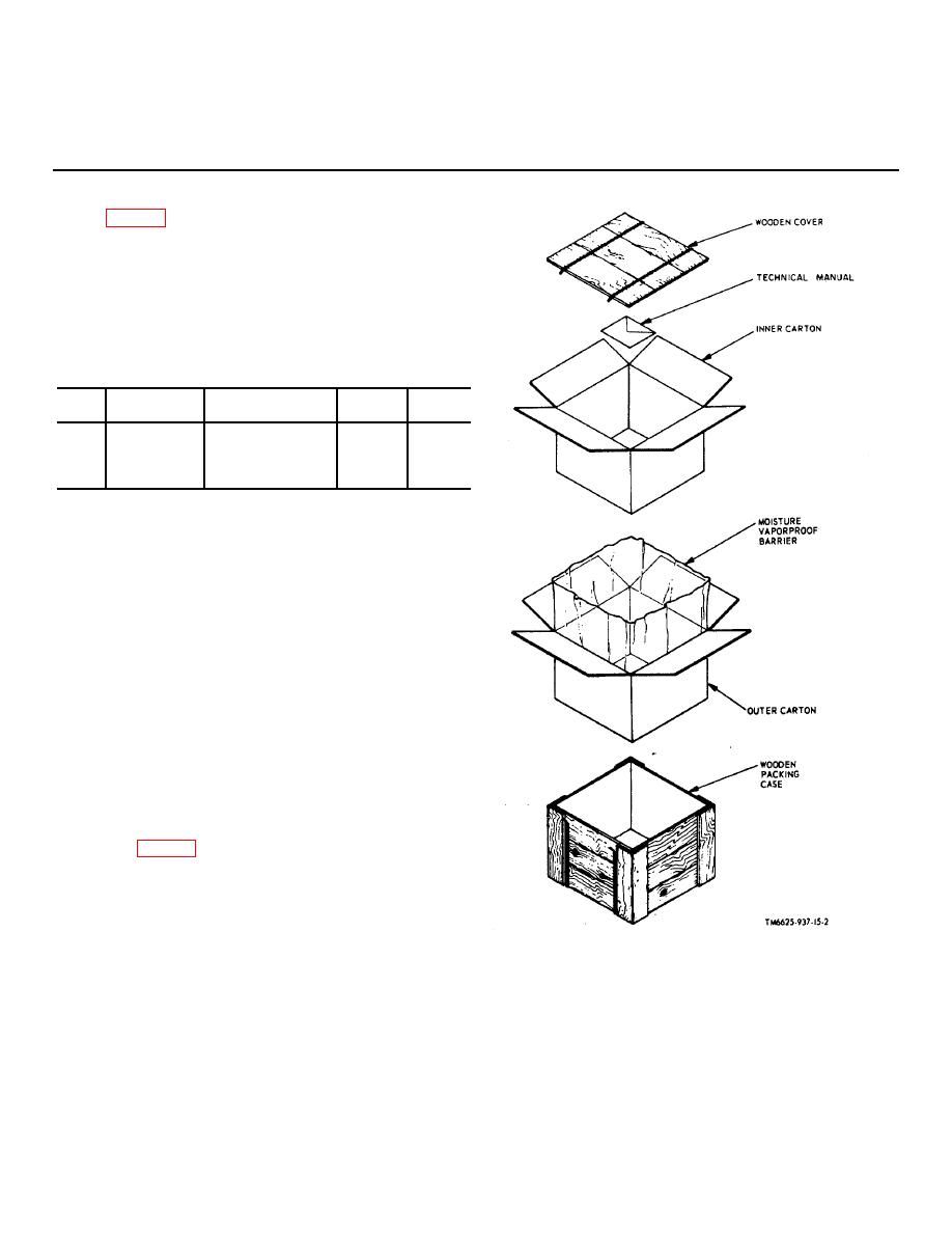
a. Packaging Data. When packed for shipment,
Indicator, Channel Alignment ID-1189/PR is placed in an
inner carton. A moisture vaporproof barrier is placed
around the inner carton. This package is placed in an outer
carton, and the outer carton is packed in a wooden box. A
typical shipping box is shown in figure 2-1. The
dimensions, volume, and contents of the shipping box are:
Box
Contents
Dimensions
Volume
Weight
No.
(in.)
(cu ft)
(lb)
1
Indicator
15 x 151/8 x 11
1.5
27
Channel
Alignment
ID-1189/PR
b. Removing Contents.
(1) Cut and fold back the metal straps.
Caution: Do not attempt to pry off the top and
side, equipment damage may result.
(2) Remove the nails from the top and one side of
the wooden packing box with a nailpuller. Remove
the top and side.
(3) Open the outer carton and the moisture-
vaporproof bag.
(4) Remove the inner carton.
(5) Open the inner carton and remove the
technical manual and the ID-1189/PR.
c. Opening Case CY-6078/PR. Place the
ID1189/PR (fig. 2-2) on a firm, flat surface. The top of the
case contains dimples. The bottom may be identified by
four pressed-out feet. Depress the red core of the breather
valve to equalize the pressure between the inside of the
case and the outside air. Pull the top of the front and rear
latches out and down as far as they
Figure 2-1. Packaging of Indicator, Channel Alignment ID-
1189/PR.
2-1
|
|
Privacy Statement - Press Release - Copyright Information. - Contact Us |
