 |
|||
|
|
|||
|
|
|||
| ||||||||||
|
|
 TM 11-6625-937-12
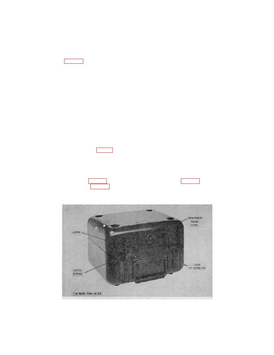
will go. Release the bottom of the front latches from their respective latch strikes and raise the cover upward and then
toward the rear. The cover remains attached to the case by the rear latch hinges.
2-2. Checking Unpacked Equipment
a. Inspect the equipment for damage incurred during shipment. If the equipment has been damaged, report the
damage on DD Form 6 (para 1-3b).
b. See that the equipment is complete as listed on the packing slip. If a packing slip is not available, check the
equipment against the basic issue items list (app B). Report all discrepancies in accordance with TM 38-750. Shortage
of a minor assembly or part that does not affect proper functioning of the equipment should not prevent use of the
equipment.
c. If the equipment has been used or reconditioned, see whether it has been changed by a modification work order
(MWO). If the equipment has been modified, the MWO number will appear on the case near the nomenclature plate. If
modified, see that any operational instruction changes resulting from the modification have been entered in the
equipment manual.
NOTE
Current MWO's applicable to the equipment are listed in DA Pam 310-7.
2-3. Installation of Battery BA-399/U
a. On early models of the ID-1189/PR the battery compartment is located beneath a cover-plate at the lower
righthand corner of the topplate assembly (fig. 2-3). Release the two battery cover fasteners by turning them one-
quarter turn counterclockwise, and remove the plate. The battery cover is connected to the battery compartment by a
cloth tape. Pull the tape tight and place the BA-339/U, connector side down and toward the top of the top plate
assembly, on top of this tape. Push the battery down, with the tape under it, and firmly seat the battery in the battery
connector at the bottom of the battery compartment. Fold the remaining tape on top of the battery and replace the
battery cover. Lock the two cover fasteners by turning them clockwise.
b. On the ID-1 189 (XE-2) /PR (fig. 3-11 and later models of the ID-1189/PR (fig. 3-19), the battery is connected to
the INTERNAL BATTERY connector (fig. 3-11), and is located on the control panel. Make certain the battery jack
connectors mate with the pins of the INTERNAL BATTERY connector, and firmly press the battery into a connected
position.
Figure 2-2. Indicator, Channel Alignment ID-1189/PR, case closed.
Change 3 2-2
|
|
Privacy Statement - Press Release - Copyright Information. - Contact Us |
