 |
|||
|
|
|||
|
Page Title:
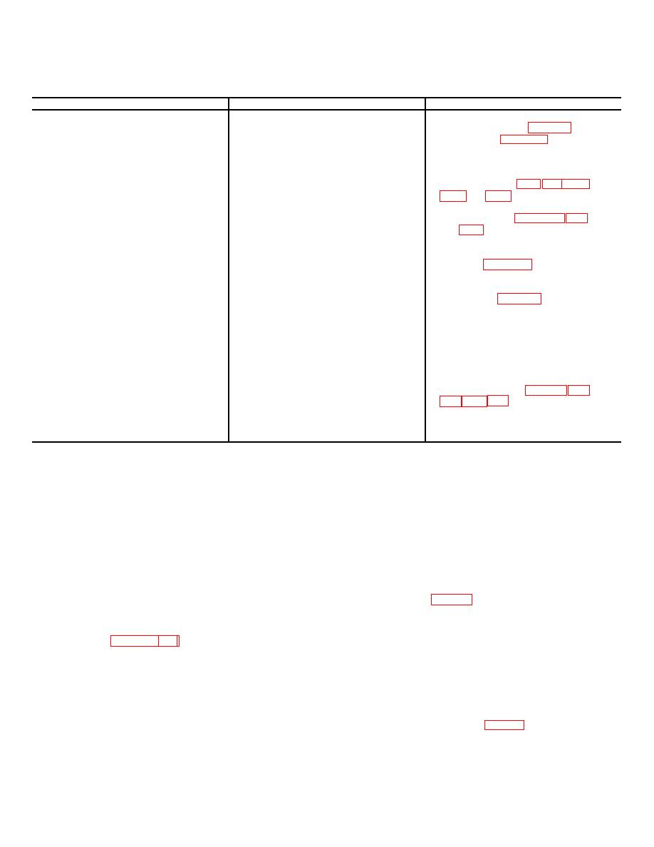
Chart 3-1. Troubleshooting-Direct Support |
|
||
| ||||||||||
|
|
 TM 5-4310-340-24
Chart 3-1. Troubleshooting-Direct Support
Malfunction
Probable Cause
Corrective Action
1. Compressor overheats.
a. Defective fan spring.
b. Defective fan.
c. Replace compressor (TM-9-2350-
components
232-20-1).
2. Relief valve activated (open).
a. Defective cooler to next higher
a. Replace defective cooler and/or
stage and/or defective af-
tercooler.
b. Defective relief valve.
b. Test relief valve by replacement
with a new valve (para 3-12. 3-1
and 3-17). Discard relief valve
removed if defective.
3. Excessive oil consumption.
a. Defective oil seals and/or
a. Replace defective seals and/or
packings.
packings (para 3-26).
b. Excessive worn internal corn-
b. Replace compressor (TM 9-2350-
ponents.
232-20-1).
4. Excessive vibration.
a. Defective fan.
b. Defective compressor.
b. Replace compressor (TM 9-2350-
232-20-1).
5. Compressor
a. Defective spline (input shaft).
a. Replace compressor (TM 9-2350-
232-20-1).
b. Replace compressor (TM 9-2350-
components.
232-20-1).
6. Insufficient air pressure in system.
a. Leaking cooler or cooler con-
a. Tighten connection or replace
nection.
cooler as required (para 1-5, 3-8,
b. Defective relief valve.
b. See item 2b.
c. Defective compressor.
c. Replace compressor (TM 9-2350-
232-20-1).
Section IIl. REMOVAL AND INSTALLATION OF MAJOR COMPONENTS
3-4. General
CAUTION
The information this section provides direct and general
support maintenance personnel with the necessary
Cap or plug all openings, after removal of
instructions to remove and install all compressor assembly
components or subassemblies from compressor,
major components and assemblies as allocated by the
in order to prevent entry of dirt into unit. Entry of
maintenance allocation chart. Removal and installation of a
dirt into unit can result in damage or malfunction
component or an assembly does not require the removal of all
of equipment.
preceding components
in the disassembly sequence.
Remove only those items necessary to permit -access to the
3-5. Fan Guard
defective components being removed. During installation of
a. Removal (fig C-3).
Remove four screws (10),
pipe threaded fittings use teflon tape. per MIL-T-27730 at
lockwashers (9), washers (8) and fan guard (7) from brackets
threads and lubricate-thread-and packings with oil per M1L-L-
(26).
23699., Torque components as specified in the assembly
b. Installation. Position fan guard (7) on brackets (26)
instructions and paragraph 1-5.
with cutaway at bottom of compressor. Aline bracket screw
holes between fan guard parallel traverse bars. Secure fan
WARNING
guard to brackets with four washers (8), lockwashers (9), and
Do not attempt to remove
or disassemble
screws (10).
pressurized equipment. Stop all equipment
operation, vent all pressure to atmosphere prior
3-6. Fan and Fan Spring
to performing work in order to prevent injury to
WARNING
personnel and damage to equipment.
Remove fan spring (18, fig C-3) with extreme
care. The spring is spring loaded and will recoil
suddenly when removed causing possible injury
to personnel.
3-2
|
|
Privacy Statement - Press Release - Copyright Information. - Contact Us |