 |
|||
|
|
|||
|
|
|||
| ||||||||||
|
|
 FUEL SYSTEM
TESTING AND ADJUSTMENT
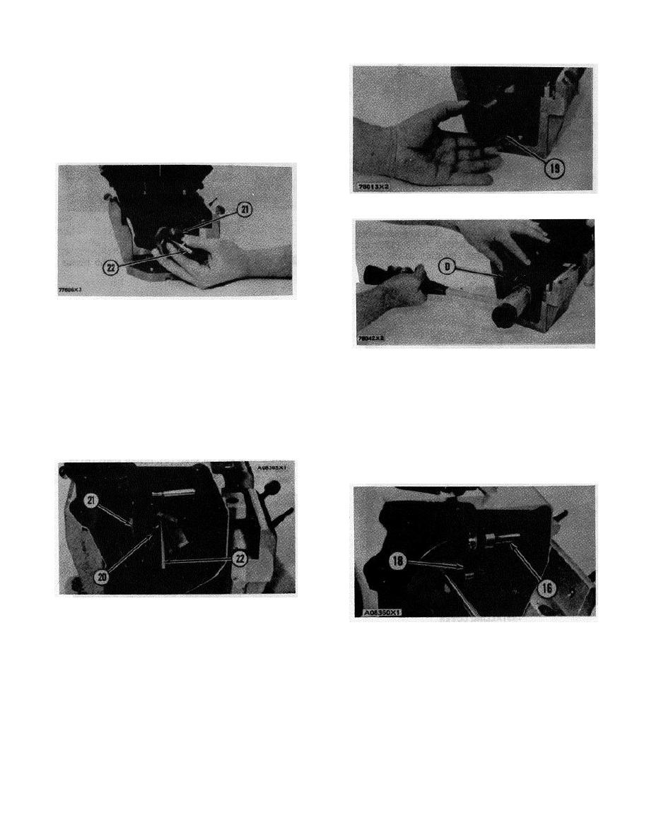
18. Remove the flyweight assembly (21) from the
camshaft.
Install Dashpot Governor
1. Put the new longer shaft (22) in flyweight assembly
(21). The new longer shaft is 5.031 in. (127.80 mm)
long.
POSITIONING SHIELD
19. Shield.
INSTALLING FLYWEIGHT ASSEMBLY
(Typical Example)
21. Flyweight assembly. 22. Shaft.
INSTALLING SHIELD
2. Put flyweight assembly (21) in position on the
(Typical Example)
camshaft.
D. 5P301 Driver.
NOTE: Be sure the dowel that holds shaft (22) is in
7. Install lever (18) on dowel (16) and install the ring that
position on the back of the flyweight assembly.
holds the lever on the dowel.
3. Install the bolts (20) that hold flyweight assembly (21)
to the camshaft. Tighten bolts (20) to 10 2 lb. ft. (1.4
NOTE: Stake shield (19) in two places, 180 degrees
0.3 mkg).
apart, around the cover in alignment with the groove in
the camshaft.
FLYWEIGHT ASSEMBLY INSTALLED
20. Bolts (three). 21. Flyweight assembly. 22. Shaft.
LEVER INSTALLED
4. Remove timing pin (C).
16. Dowel. 18. Lever.
5. Put shield (19) in position over the flyweights.
8. Install pin (14) in the pump housing.
6. Use driver (D) to install shield (19) the remainder of
the way on to the camshaft.
67
|
|
Privacy Statement - Press Release - Copyright Information. - Contact Us |