 |
|||
|
|
|||
|
Page Title:
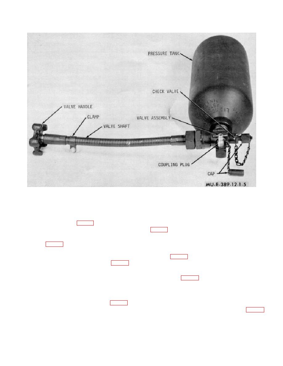
Figure 1-5. Pressure tank and valve assembly. |
|
||
| ||||||||||
|
|
 TM 3-1040-214-12
Figure 1-5. Pressure tank and valve assembly.
clamp and wingnut.
For maximum efficiency, air
safety valve contains a replaceable safety head
pressure is between 1,700 psi and 2,100 psi.
containing a disk that will rupture when air pressure
exceeds 150 psi 25 psi.
(2) Pressure regulator and tube assembly.
One end of a tube assembly (fig. 1-6) is connected to the
(5) Shutoff valve and handle. A shutoff valve
inlet side of the pressure regulator. The other end of the
tube assembly contains a quick-disconnect coupling half.
and the diffusion pipe assembly. A shutoff valve handle,
This coupling is the connection for the pressure tank
turned counterclockwise, opens the shutoff valve and
coupling plug (fig. 1-5). The pressure regulator reduces
permits pressurized air in the agent tanks and the
the air pressure coming from the pressure tank.
diffusion pipe assembly to escape through the vent tube
assembly (fig. 1-7) and into the atmosphere.
(3) Safety
valve
adapter
and
hose
b. Agent Section.
connected to the safety valve adapter.
The quick
(1) Pipe and cap assembly. The pipe and
disconnect coupling half on the other end of each hose
cap assembly (fig. 1-6) is screwed into the top of each
assembly is connected to the pipe and cap assembly.
agent tank. A hose assembly is connected to each of
Pressurized air from the pressure regulator passes
the pipe and cap assemblies. Pressurized air passes
through the safety valve adapter, hose assemblies, and
through the hose assemblies, pipe and cap assemblies,
into each agent tank.
and into each agent tank. The safety valve adapter also
(4) Safety valve. The safety valve (fig. 1-7) is
contains a second air route to relieve air pressure from
connected between the outlet side of the pressure
the agent tanks through the diffusion pipes (fig. 1-7),
regulator and safety valve adapter. The bottom of the
shut-off
1-6
|
|
Privacy Statement - Press Release - Copyright Information. - Contact Us |