 |
|||
|
|
|||
|
|
|||
| ||||||||||
|
|
 TM 3-1040-214-12
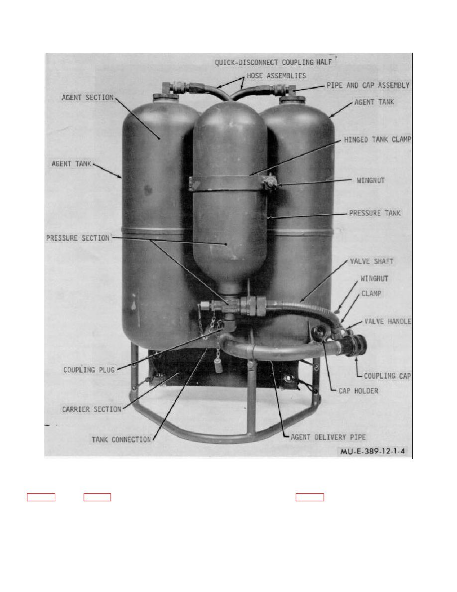
Figure 1-4. Tank group.
direct connection to the quick-disconnect coupling half
in the pressure tank. The pressure tank is strapped to
the agent tanks (fig. 1-4). A hinged tank clamp holds the
the pressure tank is disconnected from the agent
pressure tank in place. The valve shaft is clamped to
section. A valve handle connected to the valve shaft
the
body
of
the
agent
tank
with
a
operates a valve that controls the flow of pressurized air
1-5
|
|
Privacy Statement - Press Release - Copyright Information. - Contact Us |