 |
|||
|
|
|||
|
|
|||
| ||||||||||
|
|
 TM 11-6665-209-40
1-10. RADIAC SET CIRCUIT ANALYSIS
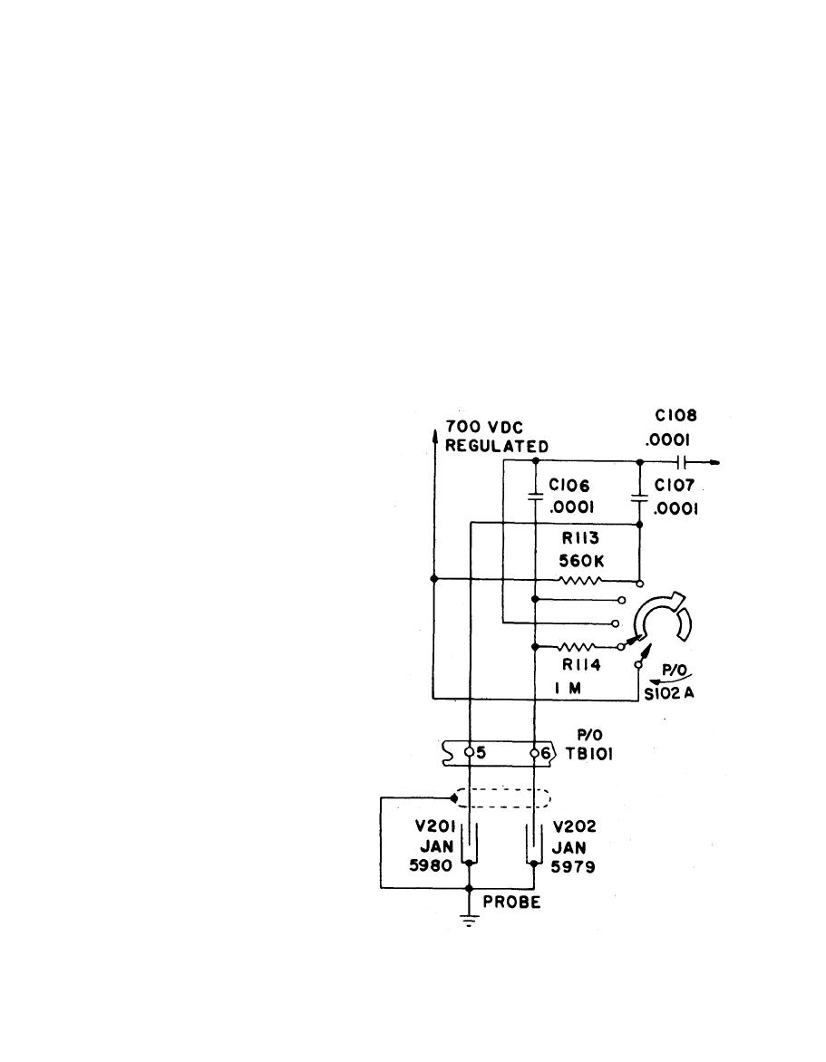
a. Detector Circuit. The detector circuit consists of G-M tubes V201 and V 2 0 2
anode load resistors R113 and R114, coupling capacitors C106 and C107, range switch
S102 and connectors.
intensity) ranges, detector V202 is disconnected from the high voltage.
(2) When switch S102 is in the 500 or 50 (mR/hr) position, regulated +700 volt DC
is applied through resistor R113 to V201 alone. When S102 is in the 5 or 0.5
(mR/hr) position, V202 is also energized through R114. When the G-M tubes
conduct under the influence of an ionizing event, a negative voltage pulse is
developed across resistor R113 or R114. This pulse is capacitively coupled to
the circuit through C106 or C107.
The output of the G-M, tubes
consist of a series of
negative-going pulses, one
f o r each ionizing event that
o c c u r s within the tube. G-M
tubes pulses having an
average duration of 80
microseconds and an average
amplitude of 100 volts are oc-
casionally encountered.
P u l s e s of reduced amplitude
and increased width occur at
the input to the circuit
because of capacitive loading
b y the cable connecting the
G-M tubes to the circuit.
Because of the low values of
C106 and C107, input pulses
a r e differentiated into very
short duration pulses. The
o v e r s h o o t associated with a
d i f f e r e n t i a t e d pulse does not
occur since the discharge
t i m e constant for the coupl-
i n g circuit is much shorter
than the charging time cons-
t a n t in the G-M tube circuit.
These negative pulses are
then coupled by V103
through C 1 0 8
|
|
Privacy Statement - Press Release - Copyright Information. - Contact Us |