 |
|||
|
|
|||
|
|
|||
| ||||||||||
|
|
 TM 11-6665-209-40
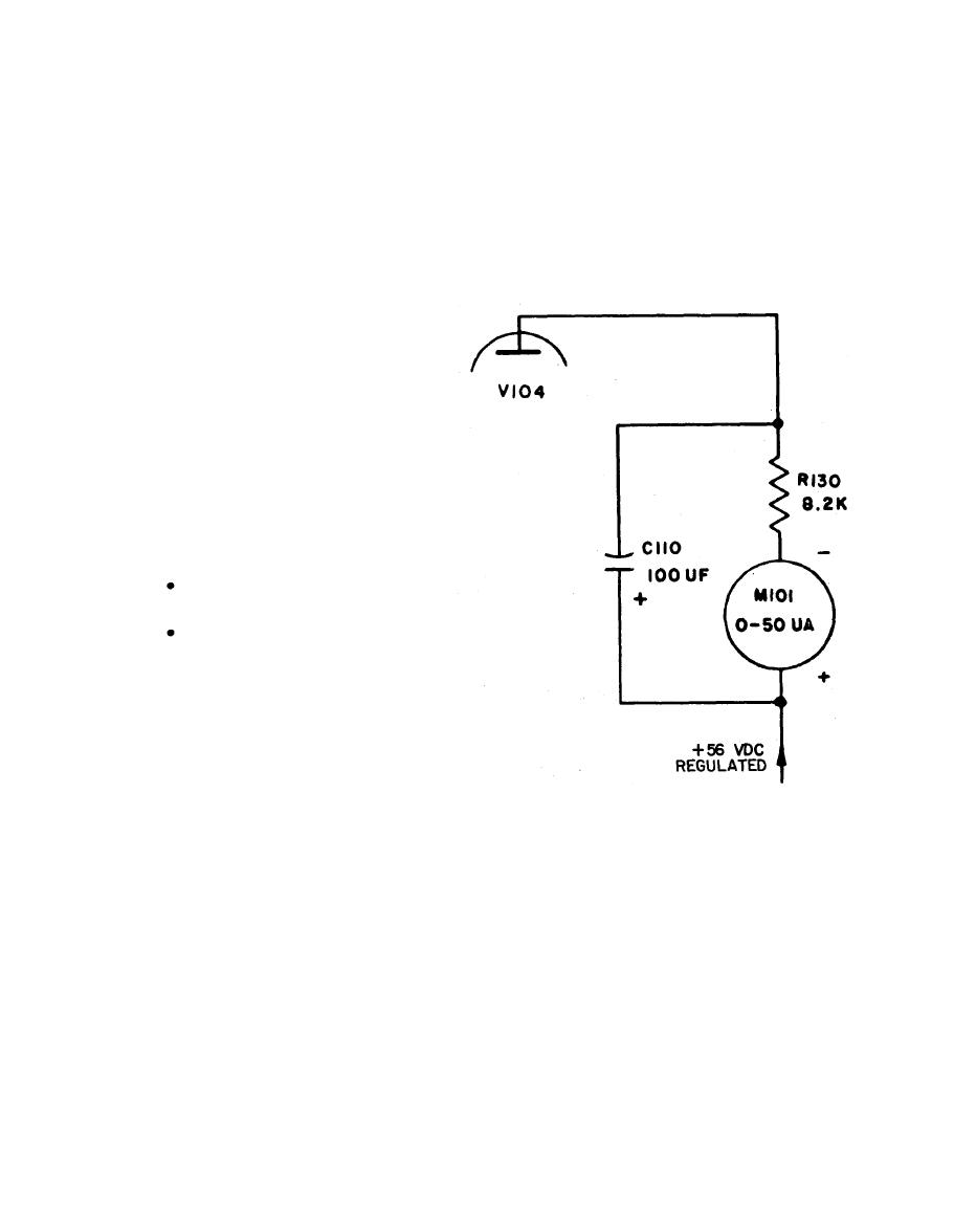
b. Indicator Circuit. The indicator circuit consists of capacitor C110, resistor R 1 3 0
a n d micrometer M101. Meter M101 and resistor R130, in series, are connected in
parallel with the capacitor. The complete circuit is connected between the plate of V 1 0 4
in the pulse-shaper and amplifier circuit and the V104 plate supply. When V104 conducts,
the current pulse charges C110 and causes a meter deflection. During the interpulse in-
terval, V104 is cut-off, and C110 discharges through R130 and M101. This condition
--
keeps the meter deflection nearly constant.
(1) The function of the indicator
circuit is to convert the output
pulses from V104 into a
relatively steady meter deflec-
tion. This deflection is propor-
t i o n a l to the radiation intensi-
ty. The pulsed output of V104
is smoothed and averaged by
C110 and R130 to form a
steady meter current. The
a v e r a g e current through the
meter depends upon the
f o l l o w i n g factors:
The number of pulses per
second received from V104.
The amplitude and duration
of each pulse.
(2) S i n c e the number of pulses
p e r second is proportional to
the radiation intensity, the
a v e r a g e meter current will be
p r o p o r t i o n a l to the radiation
intensity as long as the
amplitude and duration of
each pulse remains the same.
(3) When the range is changed through switch S102, the duration of the pulses
changes. Therefore, the meter current pulse per second also changes. This
current is proportional to the number of pulses per second. The number of
pulses per second is, in turn, proportional to the radiation intensity for a given
type of radiation. The meter scale can thus be calibrated to indicate milliroen-
tgens per hour (mR/hr) directly.
1-8
|
|
Privacy Statement - Press Release - Copyright Information. - Contact Us |