 |
|||
|
|
|||
|
Page Title:
Reference Supply, O- to 500-Volt Dc |
|
||
| ||||||||||
|
|
 TM 11-6625 -537-14-1
5-4. Reference Supply, O- to 500-Volt Dc
p o r t i o n of the output with the voltage of a
standard cell. The reference range voltage divider
uses resistor divider networks to obtain voltages
dc reference supply consists of a 500-volt dc
of 50, 5, and 0.5. These voltages are selected by
reference supply, a reference voltage range
the RAN GE switch and applied to the precision
divider and a precision voltage divider. The 500-
voltage divider which divides the input reference
volt dc reference supply is a conventional series
voltage into 500 equal steps.
r e g u l a t e d power supply with single stage
r e g u l a t i o n , It is calibrated by comparing a
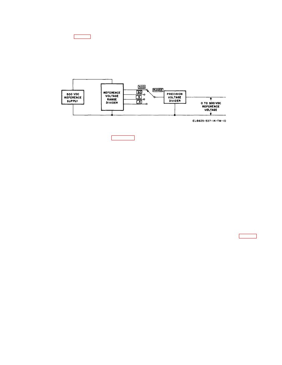
Figure 5-4. 0- to 500- volt dc reference supply, block, diagram.
V101. Voltage divider R102 and R101 maintains
Voltage from a 284 volt secondary winding of
the filaments of V101 and V105 at approximately
400 volts dc to prevent breakdown within the
p o w e r transformer T1 is converted to ap-
proximately 700 volts pulsating dc by a half-wave
tubes. The output of the power supply is set to
voltage doubler. During the positive half cycle,
500 volts by comparing a precise sample of the
CR101, CR102, and CR103 conduct to charge
o u t p u t voltage, o b t a i n e d from divider string
C 101 to the peak output voltage of the secondary.
R316, R317, REF CAL ADJ R318, and R319,
During the negative half-cycle, CR106 and CR107
w i t h the voltage of standard cell B1. In the
conduct to charge C102. Resistors R109 and R110
CALIBRATE position, levels A and B of
maintain equal voltages across C101 and C102 to
OPERATE-CALIBRATE switch S4 connect the
prevent dielectric breakdown. The voltage applied
dc vtvm to indicate the difference between the
..
to the plate of series passing tube V101 is the
standard cell voltage and the divider string. REF
total of the voltages across C101 and C102. The
CAL ADJ R318 allows the divider string to be
grid of series passing tube V 101 is controlled by
calibrated. When properly adjusted, the output of
differential amplifiers V104 and V105. Amplifier
the 500 -volt dc reference supply is 500 volt dc
V104 compares the voltage of reference tube V102
( +0.2). R e g u l a t i o n of the power supply is
with a sample of the output voltage obtained from
0.0025 percent for a 10-percent change in line
d i v i d e r string R123, C106, R124, R121 and
voltage.
C A L I B R A T E R2. The output voltage sample,
The reference voltage range divider consists of
along with the output of the power supply, is
resistance divider networks selected by RANGE
adjusted by CALIBRATE control R2. Capacitor
switch S2F and AC-de polarity switch S5G. For
C106 in the divider string decreases the sen-
t h e dc mode of operation, the output of the
s i t i v i t y of the regulator circuit to very rapid
changes in output voltage to prevent oscillation
reference voltage range divider is 500, 50, 5, or 0.5
within the supply. The outputs of V104 are ap-
volts as determined by the setting of the RANGE
switch. Level E of RANGE switch S2 connects
plied to a second differential amplifier V 105. Plate
the selected voltage divider resistor string to the
voltage for one-half of V 105 is obtained directly
output of the 500-volt dc reference supply and
from the output voltage of the power supply.
level F connects the selected divider string to the
Plate voltage for the other half of V 105 is ob-
precision voltage divider. When RANGE switch
tained from the unregulated dc through dropping
S2 is set to 500, the output of the 500-volt dc
resistors R114, R118, and R119. Capacitor C105
reference supply is directly connected to the
and resistor R 119 act as the plate load. Regulator
precision voltage divider and R322 is connected
V103 will conduct to prevent the entire
across the output of the power supply to maintain
unregulated dc voltage from being applied to
a minimum load on the power supply. Resistors
V105 if V101 ever fails. The output of V105 is
50 VDC ADJ R323, 5 VDC ADJ R326, and 0.5
applied to the control grid of series passing tube
5-7
|
|
Privacy Statement - Press Release - Copyright Information. - Contact Us |