 |
|||
|
|
|||
|
|
|||
| ||||||||||
|
|
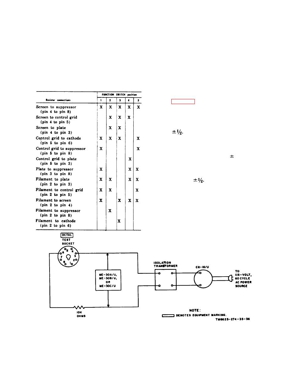
 d. Connect a. 510,000-ohm resistor (para
b. Connect a 100,000-ohm resistor (para
20b) between the pins of the OCTAL test
20b) between the pins of the OCTAL test
socket as indicated in the chart (c above), and
socket as indicated in the chart (c below),
rotate the FUNCTION SWITCH to positions
and rotate the FUNCTION SWITCH to posi-
1 through 5. The SHORTS lamp should not
tions 1 through 5.
g l o w in any combination of FUNCTION
c . The SHORTS lamp should glow in
SWITCH position or resistor connection,
the positions marked "X" when the resistor
(b above) is connected between the indicated
pins on the OCTAL test socket.
a. Set the FUNCTION SWITCH to
RANGES B and connect the equipment as
shown in figure 36.
b. Adjust the variable transformer (para
20b) so that the voltmeter indicates 50 volts,
c. Depress pushbutton 3 -- MUT. COND,
The test set meter should indicate 40 scale
divisions
Note. If the meter pointer deflects to the left, re-
verse the power cord plug of the variable transformer.
d. If the test set meter (TV-7/U only) does
connect
not indicate 40 scale divisions
the decade resistor in parallel with R113.
(1) Adjust the decade resistor so that
the test set meter indicates 40 scale
divisions
(2) Solder a resistor of the correct value
in parallel with R113.
e. When the test set meter (except for the
TV-7/U) indicates more than 40.5 divisions,
adjust R113 until the correct indication is ob-
tained.
f. When the test set meter (except for the
TV-7/U) indicates less than 39.5 divisions,
|
|
Privacy Statement - Press Release - Copyright Information. - Contact Us |