 |
|||
|
|
|||
|
|
|||
| ||||||||||
|
|
 TROUBLESHOOTING
c. Isolation. The checks listed below will
aid in isolating the trouble. After the trouble
Troubleshooting at fourth and fifth echelon
has been isolated to a particular circuit, isolate
maintenance levels includes all the techniques
the trouble within that circuit to a particular
outlined for organizational maintenance (TM
part.
11-6625-274-12) and any special or additional
(1) Resistance measurements. Use the
techniques required to isolate a defective part.
schematic diagram (fig. 42-44) to find
The field and depot maintenance procedures are
the value of the components. Use re-
not complete in themselves but are supple-
sistance measurements (para 17 and
mented by the procedures described in TM 11-
6625-274-12. The systematic troubleshooting
normal readings, and compare them
procedure, which begins with the checks that
with the readings taken.
can be performed at an organizational level,
(2) Troubleshooting chart. The symptoms
must be completed by means of additional lo-
listed in the troubleshooting chart
calizing and isolating techniques.
to a component part.
(3) Intermit tent troubles. In all these
a. General. The first step in servicing a de-
tests, the possibility of intermittent
fective test set is to localize the fault to the
troubles should not be overlooked. If
circuit responsible for abnormal operation. The
present, this type of trouble may often
second step is to isolate the fault to the defec-
be made to appear by tapping or jar-
tive part that is responsible for the abnormal
ring the equipment. Check the wiring
condition. Some faults, such as a burned-out
and connections to the test set.
resistor, can often be located by sight or smell.
The majority of faults, however, must be local-
ized by checking resistances.
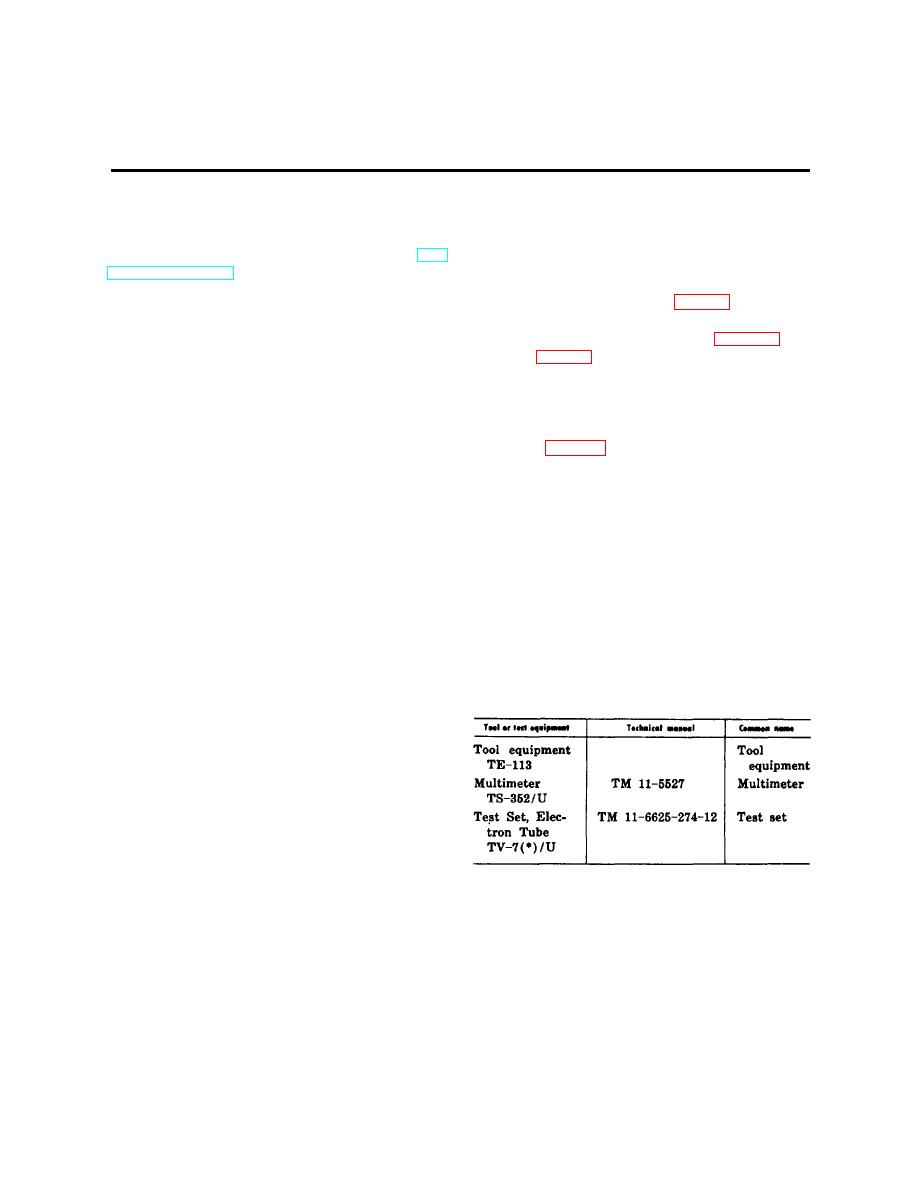
The following chart lists the tools and test
b. Localization. The test set can be used
equipment required for troubleshooting the test
to check pilot lamps, diode tubes, amplifier
set, the associated technical manuals, and the
tubes for Gm, gas, and noise, and to check tubes
assigned common names.
for shorts. The first step in localizing troubles
is to determine the circuit or circuits at fault
by the following methods:
(1) Visual inspection. The purpose of
visual inspection is to locate faults
without testing or measuring circuits.
All meter readings and other visual
signs should be observed to try to
localize the fault to a particular cir-
cuit.
a. General. In the troubleshooting chart
(2) Operational tests. Operational tests
frequently indicate the general loca-
(c below), procedures are outlined for isolat-
ing troubles to. a particular component part.
tion of trouble. In many instances,
the tests will help in determining the
The adjustment chart (d below) indicates the
exact nature of the fault. The equip-
test that is to be performed when certain com-
ment performance checklist (TM 11-
ponent parts are adjusted or replaced. Parts
6625-274-12) is a good operational
locations for the different models of the test
test.
set are shown in figures 15 through 32. Re-
20
|
|
Privacy Statement - Press Release - Copyright Information. - Contact Us |
