 |
|||
|
|
|||
|
Page Title:
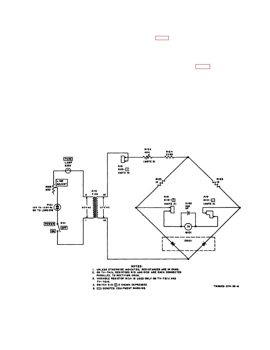
Figure 6. Simplified line voltage test circuit. |
|
||
| ||||||||||
|
|
 The total current in the circuit will
flow through the right-hand part of
CR101.
a. Shorts Test Circuit.
(2) When terminal 19 is negative with
(1) The voltage across secondary No. 2
respect to terminal 37, the left-hand
of transformer T101 is applied to a
part of CR101 will conduct and the
voltage divider consisting of resistors
r i g h t - h a n d part of CR101 will not
R107 and R108 (fig. 7). The voltage
conduct. Current will flow from ter-
across R107 is applied to the elements
minal 19 through the left-hand part
of the tube under test through C102
of CR101 to the junction of R123 and
and R109 and C105. Neon SHORTS
one part of switch S110-1. The cur-
lamp E101 is in parallel with C105
rent will divide at this point. Some of
and R109. Capacitor C105 and re-
the current will flow through R123;
s i s t o r R109 eliminate internally
the remainder of the current will flow
generated harmonics that are a result
through part of switch S110-1, meter
of operating the test set on input line
M101 and filter capacitor C103,
frequencies higher than 60 cps.
another part of switch S110-1, and
(2) The voltage across R107 is applied
R125. The total current in the circuit
to the elements of the tube under test
will flow through R124, variable re-
sistor R134, and one part of switch
when the selector switches are
S110-1 to terminal 37 of T101.
p r o p e r l y set and the FUNCTION
Figure 6. Simplified line voltage test circuit.
|
|
Privacy Statement - Press Release - Copyright Information. - Contact Us |